germoju said:hi,
sorry I'm LOST !
I made an other PCBoard and result is the same. Sound is OK, but no compression. I dont know what you do that I dont. I dont know where to search...
I changed the Attack pot and his wires... NO CHANGE.
The calibration is Ok for the step 1 and 2. but step 3, when you open compression, I dont loose any dB...
I dont know what to do now !!! Please someone has an idea ??
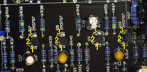
Some news pictures : http://flic.kr/s/aHsjyjg8WT
I filmed the calibration problem...=> http://youtu.be/UyxpICYOmNQ
Am I right ??


![Soldering Iron Kit, 120W LED Digital Advanced Solder Iron Soldering Gun kit, 110V Welding Tools, Smart Temperature Control [356℉-932℉], Extra 5pcs Tips, Auto Sleep, Temp Calibration, Orange](https://m.media-amazon.com/images/I/51sFKu9SdeL._SL500_.jpg)