You are using an out of date browser. It may not display this or other websites correctly.
You should upgrade or use an alternative browser.
You should upgrade or use an alternative browser.
[BUILD] 1176LN Rev D DIY
- Thread starter mnats
- Start date


Help Support GroupDIY Audio Forum:
This site may earn a commission from merchant affiliate
links, including eBay, Amazon, and others.
Echo North
Well-known member
yes RMS. And yes your P-P calculation is correct.
pittsburgh
Well-known member
Is R4 supposed to be a 270K Resistor? It's labeled on the PCB and sheet as a 270R, but under the description it says 1/4W resistor.
I have a 270K resistor here and don't see another place for it to go, just want to make sure before I solder it in place.
-P
I have a 270K resistor here and don't see another place for it to go, just want to make sure before I solder it in place.
-P
no R4 is 270. not 270kpittsburgh said:Is R4 supposed to be a 270K Resistor? It's labeled on the PCB and sheet as a 270R, but under the description it says 1/4W resistor.
I have a 270K resistor here and don't see another place for it to go, just want to make sure before I solder it in place.
-P
270k go to the release pot.
did i see you zeroing the meter with the front panel adjustment? YESsr1200 said:yeah, step 1 should have the jumper IN, also... did i see you zeroing the meter with the front panel adjustment? 44 is for the tracking adjust, and 71 is for the 0 adjust (right?)
44 is for the tracking adjust, and 71 is for the 0 adjust (right?) YES
but you mean R44 (tracking adjust) with the front panel adjustement ? and and R71 (0 adjust) with 2k trimmer ?
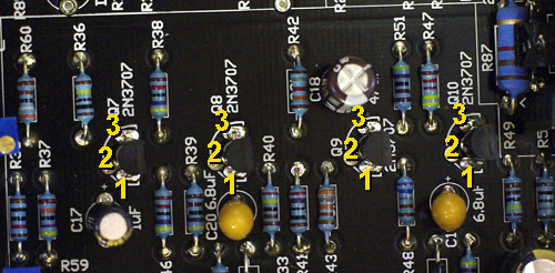
_IGP5004 par volcanovap, sur Flickr
Q1 = G -0,39v - S 0v - D 0v
Q2 = 1 0,55v - 2 1,79v - 3 0,88v
Q3 = 1 1,17v - 2 11,5v - 3 1,79v
Q4 = 1 0,43v - 2 4,03v - 3 0,98v
Q5 = 1 2,74v - 2 24,6v - 3 3,0v
Q6 = 1 2,18v - 2 2,76v - 3 27,4v
Q7 = 1 3,95v - 2 14,72v - 3 4,22v
Q8 = 1 14.25v - 2 29.9v - 3 14.72v
Q9 = 1 2,89v - 2 16,44v - 3 3,42v
Q10 = 1 16,42v - 2 29,9v - 3 16,46v
Q11 = G -0,26v - S -0,57v - D 8,29v
Q12 = 1 -1,2v - 2 6,28v - 3 -0,57v
Q13 = 1 -1,33v - 2 6,28v - 3 -0,73v
Q14 = 1 11,05v - 2 29,9v - 3 11,51v
R87 = 29,9v
CR6 = -9,7v
Can you see something wrong ?

Q1 or/and Q11 maybe ??


![Soldering Iron Kit, 120W LED Digital Advanced Solder Iron Soldering Gun kit, 110V Welding Tools, Smart Temperature Control [356℉-932℉], Extra 5pcs Tips, Auto Sleep, Temp Calibration, Orange](https://m.media-amazon.com/images/I/51sFKu9SdeL._SL500_.jpg)


Echo North
Well-known member
Did you test the output to see if it's compressing like I'd suggested?
Echo North said:Did you test the output to see if it's compressing like I'd suggested?
i'm totally bad with that.... I dont know. The only result I had is 0.0v
I mesure it with V= .2
One pin of the multimeter is on pin2 of XLR output, the other is on the pin3 of the XLR output.
I have something with V~200 but it's not good precision.
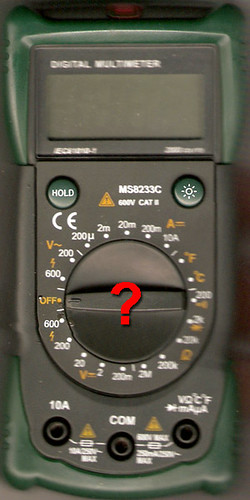
multimetre par volcanovap, sur Flickr
Echo North
Well-known member
Do it with your DAW. Look at the output in your DAW to see if it's compressing. We need to confirm that a) the unit is compressing and it's a meter circuit issue or b) the meter is right and it's not compressing.
Also did you do the pad 22 blk/grn continuity tests I mentioned earlier. We need to confirm your side chain isn't shorted to ground.
Also did you do the pad 22 blk/grn continuity tests I mentioned earlier. We need to confirm your side chain isn't shorted to ground.
Do it with your DAW. Look at the output in your DAW to see if it's compressing. We need to confirm that a) the unit is compressing and it's a meter circuit issue or b) the meter is right and it's not compressing.Echo North said:Do it with your DAW. Look at the output in your DAW to see if it's compressing. We need to confirm that a) the unit is compressing and it's a meter circuit issue or b) the meter is right and it's not compressing.
Also did you do the pad 22 blk/grn continuity tests I mentioned earlier. We need to confirm your side chain isn't shorted to ground.
Yes I tried to make the test you told me... but I cant understand...
Anyway, when I turn ON the attack button, I can't hear any compression. I can't see any dB drop....
Also did you do the pad 22 blk/grn continuity tests I mentioned earlier. We need to confirm your side chain isn't shorted to ground.
I think that OK. take a look to my video here : http://youtu.be/Iezi-JH3y6A
This is kind of odd, but i got mine to do the same thing last night again after we chatted. On step 3 of the calibration, as a test, turn your input all up. Then bring your output up to meet 0. Turn the attack off and see what happens. If you do the opposite, the compressor doesnt have enough signal to compress anything so therefore the meter not moving is correct.
pittsburgh
Well-known member
Is R77, (8.2K), located on the meter PCB? There is a 8.2K marked on that board, but it doesn't say R77.
Echo North
Well-known member
Yes.
I left the designations off because the boards are for several different revisions.
I left the designations off because the boards are for several different revisions.
pittsburgh
Well-known member
Thanks!
pittsburgh
Well-known member
I'm looking for R63 on the ratio board. R63 is a 1.5K resistor. Is it supposed to fit in R6 on the ratio board? Do the numbers on the right hand side correspond to pad levels?
Echo North
Well-known member
pittsburgh said:I'm looking for R63 on the ratio board. R63 is a 1.5K resistor. Is it supposed to fit in R6 on the ratio board? Do the numbers on the right hand side correspond to pad levels?
Look here:
http://www.hairballaudio.com/docs/FET%20Compressor%20PCB%20Board%20Info%20V3.pdf
It's R4
sr1200, my hero !
thank you so much ! MY 1176 WORKS !
after some hours testing everything, sr1200 make me test the ratio board : BINGO !
I had a problem on the ratio board between pin4 and middle of the switchs :
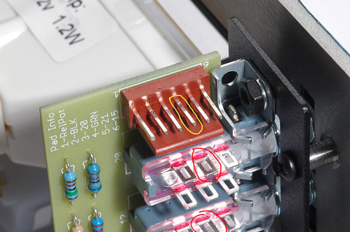
molex_header_ratio_board2 par volcanovap, sur Flickr
not connected... I add some soldier but nothing change... so sr1200 told me to make a bridge between pin4 and pin on a middle of the 20.1 switch. Now they're connected So we finished the calibration and compression was born ! ;D
I'll show you with a picture tomorrow. (better than my english...)
for sure, now I got one 1176LN and one PCB alone. I have to re-order hairball-audio
THANKS YOU EVERYBODY FOR YOUR HELP
thank you so much ! MY 1176 WORKS !
after some hours testing everything, sr1200 make me test the ratio board : BINGO !
I had a problem on the ratio board between pin4 and middle of the switchs :
molex_header_ratio_board2 par volcanovap, sur Flickr
not connected... I add some soldier but nothing change... so sr1200 told me to make a bridge between pin4 and pin on a middle of the 20.1 switch. Now they're connected
So we finished the calibration and compression was born ! ;D I'll show you with a picture tomorrow. (better than my english...)
for sure, now I got one 1176LN and one PCB alone. I have to re-order hairball-audio
THANKS YOU EVERYBODY FOR YOUR HELP
Echo North
Well-known member
Awesome job guys!
yeah, i was starting to take it personally. lol we tested EVERYTHING on his board... NOTHING was wrong. We get to the ratio board and i guess the trace on the board was broken somehow... Its a helluva lot easier to trouble shoot when you have a working unit to compare to. Skype is the real hero here LOL
Skype is the real hero here LOLEcho North
Well-known member
sr1200 said:yeah, i was starting to take it personally. lol
Ha! I've definitely been there.
Similar threads
- Replies
- 5
- Views
- 573
- Replies
- 2
- Views
- 557