You are using an out of date browser. It may not display this or other websites correctly.
You should upgrade or use an alternative browser.
You should upgrade or use an alternative browser.
[BUILD] 1176LN Rev D DIY
- Thread starter mnats
- Start date


Help Support GroupDIY Audio Forum:
This site may earn a commission from merchant affiliate
links, including eBay, Amazon, and others.
Great to hear your unit is working : )germoju said:sr1200, my hero !
thank you so much ! MY 1176 WORKS !
after some hours testing everything, sr1200 make me test the ratio board : BINGO !
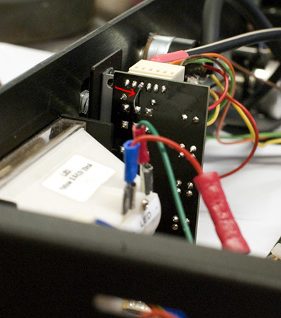
I had a problem on the ratio board between pin4 and middle of the switchs :
molex_header_ratio_board2 par volcanovap, sur Flickr
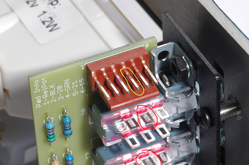
not connected... I add some soldier but nothing change... so sr1200 told me to make a bridge between pin4 and pin on a middle of the 20.1 switch. Now they're connectedSo we finished the calibration and compression was born !
I'll show you with a picture tomorrow. (better than my english...)
for sure, now I got one 1176LN and one PCB alone. I have to re-order hairball-audio
THANKS YOU EVERYBODY FOR YOUR HELP
Just curious, what was wrong in the end? Was it the PCB board, bad switch, bad connector or bad solder that caused this particular issue that you had to jump it? Maybe someone else might find the cause useful when they are troubleshooting.
canidoit said:Just curious, what was wrong in the end? Was it the PCB board, bad switch, bad connector or bad solder that caused this particular issue that you had to jump it? Maybe someone else might find the cause useful when they are troubleshooting.
I think my solder was good... the signal doesn't pass between pin2 of 20.1/12.1/8.1/4.1 and pin4 of the switch. I resolder it but nothing change. The bridge was the best solution :
_IGP5077 par volcanovap, sur Flickr
dbonin
Well-known member
I did the q-bias calibration, no problems.
The meter circuit adjustment? Not so much.
I'm using the 2k pot for the "0" set and the 2k trim on r75.
Ignoring the VU meter, the best I can do is 0.50 v on r74. No matter what I do I can't get r74 down to 0v, let alone with the VU near zero.
When I dial in .5 V on r74 the VU needle is pegged past +3.
I've read others have had luck with a 5k trim on r75? If i just get a 5k trim and I get the calibration to work am I just masking some other issue I have introduced earlier, or is that moot at this point?
Thanks for any pointers!
If the trimmers are far out of whack before starting calibration (ie if you turned them all the way ccw or cw) you can get this scenario. Go back to step 1. Set all your trimmers to about 50% and start over, see if that helps.
dbonin
Well-known member
thanks Sr1200.
I think I have much bigger fish to fry - when I apply a .775 volt input signal (sine wave), set the buttons to GR, crank up the input gain to about half, then as I slowly turn up the output my transformers begin to ring. Not sure yet if it's just the power or the output xformer or both.
Power supply test point voltages are spot on, but dc measurements taken on a few transistor legs don't match mnats voltage schematic.
Will be reviewing parts and values again section by section tonight... so far all external wiring looks good. I measured every resistor b4 instaling and I tracked/recorded every part to it's place as I placed them - if I did swap a part I'll be able to find it tonight.


![Soldering Iron Kit, 120W LED Digital Advanced Solder Iron Soldering Gun kit, 110V Welding Tools, Smart Temperature Control [356℉-932℉], Extra 5pcs Tips, Auto Sleep, Temp Calibration, Orange](https://m.media-amazon.com/images/I/51sFKu9SdeL._SL500_.jpg)
Thats perfectly normal, you should hear the tone you're putting into the unit.
hey guys
I got some question about my unit. I try with a mono drum and I loose my low-end, the kick loose ~20dB. I can hear like a low cut at 250hz~300hz. All the rest is good between 300hz to 20khz.
Is it an error ? Does somebody had the same problem ? Can I do something ? Did I forget something ?
Thanks
I got some question about my unit. I try with a mono drum and I loose my low-end, the kick loose ~20dB. I can hear like a low cut at 250hz~300hz. All the rest is good between 300hz to 20khz.
Is it an error ? Does somebody had the same problem ? Can I do something ? Did I forget something ?
Thanks
pittsburgh
Well-known member
Are R22 and R21 supposed to be touching on the ratio board? I'm pretty sure I didn't bridge the joints while soldering, but am getting audible continuity when testing.
pittsburgh
Well-known member
I'm coming to the conclusion that resistors for the ratio PCB board are not a part of the Mouser parts list. Is that right?
Echo North
Well-known member
pittsburgh said:I'm coming to the conclusion that resistors for the ratio PCB board are not a part of the Mouser parts list. Is that right?
No they should be in the BOM.
dbonin
Well-known member
pittsburgh said:I'm coming to the conclusion that resistors for the ratio PCB board are not a part of the Mouser parts list. Is that right?
are you doing push buttons or rotary switches? If buttons, you can disregard the small boards that came with the mnats kit and use the ratio boards that came with the hairball kit - all the same resistor values go on the ratio board from hairball.
dbonin
Well-known member
sr1200 said:Thats perfectly normal, you should hear the tone you're putting into the unit.
Really? Normal? I assume it has something to so with the purity and frequency of the sine wave? I can't imagine it rings like that when feeding it vocal material via mic->preamp->1176??
Ok, so I'll leave that alone for now - on to a visual parts check and DC voltage tracking according to mnats voltage schematic.
Thanks!
Stagefright13
Well-known member
germoju the orange and yellow wires on the output transformer need to be soldered together.
John
John
Stagefright13 said:germoju the orange and yellow wires on the output transformer need to be soldered together.
John
thanks... I did not solder them. The contact must be bad. I will fix this ! Thanks !
pittsburgh
Well-known member
So just to clarify, if I'm using the push button system for the ratio, I need to use the hairball PCB and disregard the MNATS ratio/meter board?
germoju said:Stagefright13 said:germoju the orange and yellow wires on the output transformer need to be soldered together.
John
thanks... I did not solder them. The contact must be bad. I will fix this ! Thanks !
arrrrfff... I think I got a new problem... I re-soldered the orange and yellow wires on the output transformer. Nothing changed ! I got a real big low-cut maybe at 300 hz
Echo North
Well-known member
pittsburgh said:So just to clarify, if I'm using the push button system for the ratio, I need to use the hairball PCB and disregard the MNATS ratio/meter board?
Correct.
dbonin
Well-known member
regarding http://mnats.net/files/1176REVD_VOLTS.pdf
aside from turing the power on, is there anything that needs to be done prior to testing the points? No input signal applied?
Also, if I'm using 3708's and he was using something else, would that cause the voltages to be way off?
I assume as long as they are in the same ball park we're ok?
I'm testing all points with my common lead on ground pad 16...
germoju said:germoju said:Stagefright13 said:germoju the orange and yellow wires on the output transformer need to be soldered together.
John
thanks... I did not solder them. The contact must be bad. I will fix this ! Thanks !
arrrrfff... I think I got a new problem... I re-soldered the orange and yellow wires together on the output transformer. Nothing changed ! I got a real big low-cut maybe at 300 hz
Did someone had the same problem ?
Similar threads
- Replies
- 5
- Views
- 572
- Replies
- 2
- Views
- 557