[BUILD] 1176LN Rev D DIY

GroupDIY Audio Forum

Help Support GroupDIY Audio Forum:

This site may earn a commission from merchant affiliate links, including eBay, Amazon, and others.
Thanks Echo North and edward! Indeed I am learning alot on this forum and with this build! I appreciate the help! Kind regards
 
Potentially noob question.....

Where do I use the two smaller boards (the ones with S3 and S2) that came with the main pcb?

Do I use them? I dont see them being used anywhere? i have stuffed them with parts from my BOM?

Pleeeeeeeeease help????
 
Please dont take this as me being an @$$ but...
I understand theres like over a hundred pages on this thread, but that's what the bottom search box is for up top.  Also, EVERYTHING you need is either going to be on
www.mnats.net
or
www.hairballaudio.com

Please read the MNATS site THOROUGHLY. and if you're using the hairball kit, read the build info on that site and all your questions will be answered.

If you're still stumped after searching and reading those pages, I'll be happy to help ya.  (just ask germoju)  ;)


SR1200, I hear you bro!

I found the info I needed 2 pages from this one. lol  :-[

Im doing the Button ratio so I just need to disregard the mnats boards and use the hairball boards. I went and stuffed the mnats boards already so I geuss I got a bit of "de-soldering" to do!

Thanks again!

(Power section questions coming soon) BEWARE!!! LOL!

Cheers for now!
 
Ok guys, here is my last question for now.

I struggle to find the exact material where I stay to use for wiring my project BUT I have mined some 20AWG cable from a PC Power supply. I have been using it so far...... Would it be suffecient? I know its not the recommended 22AWG but will this suffice?

Regards
 
ILOVE1176 said:
Ok guys, here is my last question for now.

I struggle to find the exact material where I stay to use for wiring my project BUT I have mined some 20AWG cable from a PC Power supply. I have been using it so far...... Would it be suffecient? I know its not the recommended 22AWG but will this suffice?

Regards

The only reason I recommend 22AWG is because it generally fits well into the solder pads.  I would say the best wire to use is free wire!  :)

For the safety ground connection I like to use something a little bulkier to be safe.  Like a 16AWG or something.
 
Echo North said:
Also, using your meter, test to make sure that GRN on the ratio PCB has continuity to pad 22 on the main board and NO continuity to BLK (ground) when in GR mode.
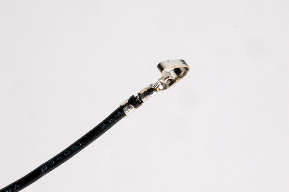
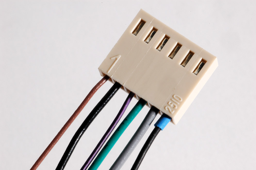
These are my readings - Just to be sure I'm reading this right:

GR on:

  • continuity from pad 22 to GRN on ratio
    No continuity from pad 22 to BLK on ratio

This looks right - still no joy on second calibration.

Any other pointers on where/what to trouble shoot for the meter calibration?

Thanks!
-Don
 
hi guys...

someone knows the Mouser reference for this piece ?????

molex_connector_wire_socket.jpg


I ordered some but too big... I can't find by myself... Can you help me ??

Thanks'
 
sr1200 said:
depends on how big the piece you're fitting it into is.  Without knowing the size of the connector, cant give you a part.
hi you !!
it's for the ratio board... For my first unit I make a trick but I's like to be clean with that... :
ratio_molex_assembly_completed.jpg
 
dbonin said:
I did the q-bias calibration, no problems.
The meter circuit adjustment?  Not so much.
I'm using the 2k pot for the "0" set and the 2k trim on r75.

Ignoring the VU meter, the best I can do is 0.50 v on r74.  No matter what I do I can't get r74 down to 0v, let alone with the VU near zero.
When I dial in .5 V on r74 the VU needle is pegged past +3.

I've read others have had luck with a 5k trim on r75?  If i just get a 5k trim and I get the calibration to work am I just masking some other issue I have introduced earlier, or is that moot at this point?

Thanks for any pointers!

The VISHAY trimmers in the latest BOM from hairball - are they the same as the BOURNS trimmers?  Need to go back and check on mouser since i installed my VISHAY trims just like the bourns, perpendicular to the screen.

 
dbonin said:
regarding http://mnats.net/files/1176REVD_VOLTS.pdf
aside from turing the power on, is there anything that needs to be done prior to testing the points?  No input signal applied?

Also, if I'm using 3708's and he was using something else, would that cause the voltages to be way off?

I assume as long as they are in the same ball park we're ok?

I'm testing all points with my common lead on ground pad 16...

Bump - any suggestions?  So far, the only voltage test points that are out of wack are those on the transistor Q13 which connects to the trimmer at R75....  no big surprise there?  I'm going to replace the 3708 transistors that are supposed to match, just for grins.

Anyone have any additional pointers?

Thanks!
-Don
 
Hi all,
I'm near to finish my rev D comp, but i need your help and advices cause my PCB is the first version of Mnats.
i like to clear this point, before soldering the transitor. i prefer to take my time and don't waste hours and days of troubleshooting.
Here is the obscur points
1) the PCB version 1 doesn't have additional footprints for the 2N5088. Ok, Q12 & 13 must be matching at 10% of HFE. but i don't know if HFE need to be superior to 250?
2) i ordered some 2N5088 for Q7, 8, 9 10, i'm still not sure hw to place the 2N5088 on the pcb, so i add a picture for show what i undersand, can you confirme if i'm right

3) the last question, on the PCB version the jumper is missing. For the moment , i don't put R44. So i don't know how to do the calibration of the Vumeter. any advice are welcome.
Thanks you for your help...

Best
Cyril
 

Attachments

  • 1176_rev_d_pcb_gr_control_cu_lab-1.jpg
    1176_rev_d_pcb_gr_control_cu_lab-1.jpg
    276.7 KB
ON ver 1 (as i understand it) there is no trim pot, its just a resistor which you leave OUT until calibration time.  As far as the orientation of the transistors, I dont know if that has changed over the revisions, but I know MNATS has an overlay you can look at on his website.  http://mnats.net/files/1176LN_REVD_V2.2_DOC.pdf Print it out and lay it next to your board as your work.

I would think that following the latest version would be the same.  As far as i know only a few resistor values and that trimmer at R44 has changed.

As indicated on the original schematic, some details regarding the transistors should be noted. Select Q12 and Q13, matching hFE within 10% (the absolute value is not critical). This will allow proper calibration of the meter driver circuit and correct operation once calibrated.

Q7 through Q10 must be selected for an hFE of 250 or above.

Correct me if im wrong but:
Even though there is only a resistor spot on the board, YOU CAN put a trimmer in there if you want to be a bit brave (doesn't involve drilling or anything) if you can get your hands on another rheostat (that you use for the front 0 adjust) you can wire the wiper to one side of the resistor pad R44, pin 1 or 3 to the other resistor pad of R44, and which ever is left to a ground point.  I would pre trim it to about the value of R44 before firing it up the first time. Theres no place to mount it (in theory you could drill a hole and mount it to the side panel near the input TX and have it stick out a bit if you wanted to make it accessible and not floating around in the case.)
 
Hi sr1200,
thanks for reply,
On ver 1, the trimpot(R44) is present, but the missing part is the jumper near R44. so the calibrating the VUmeter is not easier.
it's good idea to mount R44 (temporary), outside the board for the calibration process, good tips ;)

Now, still to find the right position for the 2N5088s on the PCB

Best
Cyril
 
Back
Top