sr1200
Well-known member
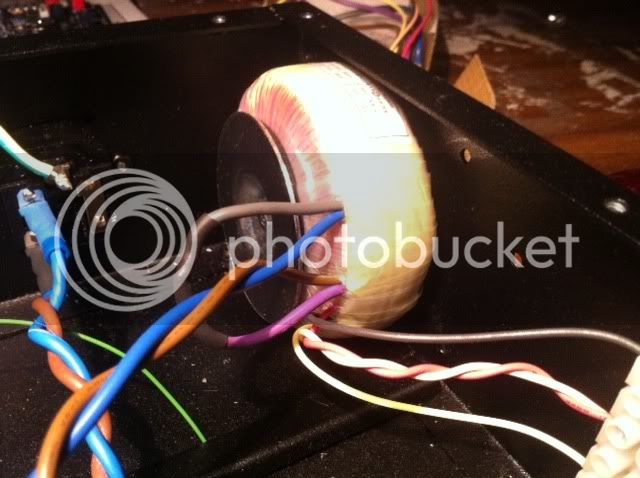
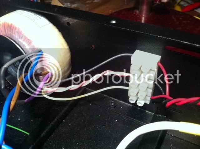
check the wiring on your input transformer next.


Echo North said:Basically do the meter tracking adjustment without adjusting the meter.
Do this ignoring the VU meter on the front.
Input = "24" mid rotation
Output = "24" mid rotation
Attack = full CW
Release = full CW
Compression ratio = 20:1
Meter mode = "GR"
1. Apply a signal (1 KHz, 0db).
2. Set output control for 0db as read on an external meter measuring AC volts across output XLR pin 2 and 3
3. Set attack full CCW (off position). Set input control for +10db as read on an external
meter measuring AC volts across output XLR pin 2 and 3
4. Turn the attack control OFF (CCW) and readjust the output level control for "0" if
necessary.
5. Repeat 7 & 8 until the output drops 10dB (2.44V to 0.775V) whenever the attack control is turned ON.
If you can do this, your unit is compressing and there is something wrong with the meter control section.
hi guysStagefright13 said:germoju Only guessing but thoroughly check your output transformer wiring. If you used screw terminals it will cover up the color legend on the board. So use the layout pic.
John
")
ILOVE1176 said:Hey everyone
I need a little help and direction.
Where do I find the info regarding which resistors and capacitor to connect to my attack and release potentiometers? I cant seem to find this info anywhere for my REVISION D BUILD.
Just confirm the following for me as well please.
Linear SPDT 25K Potentiometer = ATTACK (CORRECT?)
Linear 5M Potentiometer = RELEASE (CORRECT?)
Thanks in advance.
ILOVE1176 said:Thanks Edward!
Do you perhaps have a link to that schematic for me? Is it the PDF on mnats site? Ive gone through that and don't seem to see it?
One other thing I have noticed is my Input dial doesnt seem to go all the way round from 0 to infinity. Is this just how it is? Is the T-attenuator not eaxtly accurate with the print on the face?
ILOVE1176 said:I have no experience reading scematics drawings?
Enter your email address to join:


![Electronics Soldering Iron Kit, [Upgraded] Soldering Iron 110V 90W LCD Digital Portable Soldering Kit 180-480℃(356-896℉), Welding Tool with ON/OFF Switch, Auto-sleep, Thermostatic Design](https://m.media-amazon.com/images/I/41gRDnlyfJS._SL500_.jpg)


