dbonin said:
mattvon said:
mnats said:
mattvon said:
...if I set the input pot at "24" and slowly increase the output pot from full CCW, turning CW, I get a peak of just barely over 1.0 VAC and then it diminishes back to near 0 VAC at full CW.
That isn't normal, and you'll have to correct the problem before you can proceed with any of the calibration procedures.
What have you tried so far of the troubleshooting tips from my FAQ?
Thanks very much for your reply. Following the Hairball guide, I built the power supply first and it tests good, all voltages appear correct. I tested each resistor as I stuffed the PCB and feel confident the values are correct. I've visually inspected my solder joints, I reflowed a couple which looked questionable, so I'm thinking it's either a wiring issue or something I'm not thinking of (faulty component?)
I have also built a version of Mark Burnley's signal tracer. Since I'm not passing very much voltage, would you recommend I begin by checking voltages or testing the signal path? I'm still mostly a newbie, but I'm committed to getting this working and I'll be grateful for any advice you might have.
Check for the simple things first when it comes to wiring - it's easy to get turned around and swap wires and leads and put similar looking pots in the wrong spots. A quick glance can sometimes fool the eye into thinking something is correct when it's reversed. But lets assume you have beat that horse to death!

Start at the point where the input transformer enters the PCB - apply your .775V / 1khz test signal and measure the voltage as you increase the input pot from full ccw to full cw - (if you used terminals for the wiring, disconnect them) - let us know what you find.
Thanks for the reply! Here are my measurements (along with my signal path measurement points, to make sure I've not goofed something up):
Signal generator set to deliver a 1khz tone at .770, measured at pin 2 of the input XLR.
Measurement at the input "+" of the L-pad PCB = .770VAC
Measurement at the output "+" of the L-pad PCB, fully CCW = .770VAC
Measurement at the output "+" of the L-pad PCB, fully CW = .770VAC
Measurement at the input "+" of the input transformer PCB, L-pad fully CCW = .773VAC
Measurement at the input "+" of the input transformer PCB, L-pad fully CW = .774VAC
Measurement at the point where the "+" wire connects to the PCB (wire detached from terminal), L-pad fully CCW = .317VAC
Measurement at the point where the "+" wire connects to the PCB (wire detached from terminal), L-pad fully CW = .317VAC
I don't believe it makes a difference, but the unit was not powered up for the above measurements.
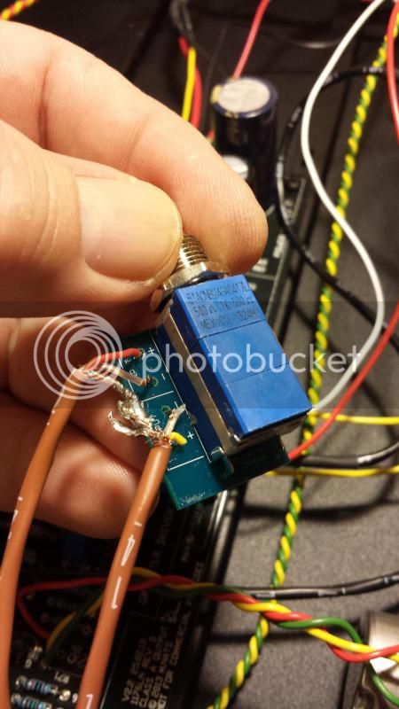
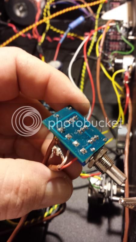
The L-pad doesn't seem to be doing anything? FWIW, I have continuity from the input transformer case to any ground point on the chassis.
Thoughts? I double-checked the L-pad wiring, it's wired correctly, grounds tied together, etc.


![Soldering Iron Kit, 120W LED Digital Advanced Solder Iron Soldering Gun kit, 110V Welding Tools, Smart Temperature Control [356℉-932℉], Extra 5pcs Tips, Auto Sleep, Temp Calibration, Orange](https://m.media-amazon.com/images/I/51sFKu9SdeL._SL500_.jpg)

