dbonin said:
mattvon said:
Ok, thanks for helping me to understand the ground relationship. When I referred to the ground near the L-pad, I meant the bare wire from pin 1 of the XLR.
I've checked and verified that I have .775VAC at the XLR by using one DMM lead on pin 2 and one DMM lead on pin 3.
I then checked and verified that I have .775VAC between the wire from pin 2 and pin 3 of the XLR before I soldered these wires to the L-pad.
As soon as I connect the wire from pin 2 of the XLR to the "+" pad on the L-pad input and the wire from pin 3 of the XLR to the "-" pad on the input side of the L-pad, I get 0.00VAC at pins 2 and 3 of the XLR (as well as the "+" and "-" input pads of the L-pad).
I also get 0.00VAC when measuring between the "+" and "-"at the output pads of the L-pad.
Rotating the L-pad fully CCW or CW has no effect on this reading.
I checked and verified once again that I have .775VAC coming out of my signal generator.
Thanks for everyone's help and patience with this.
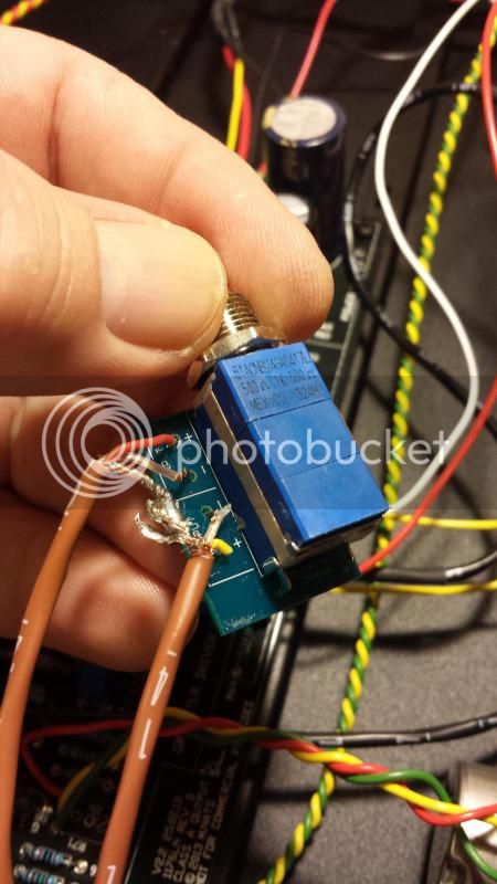
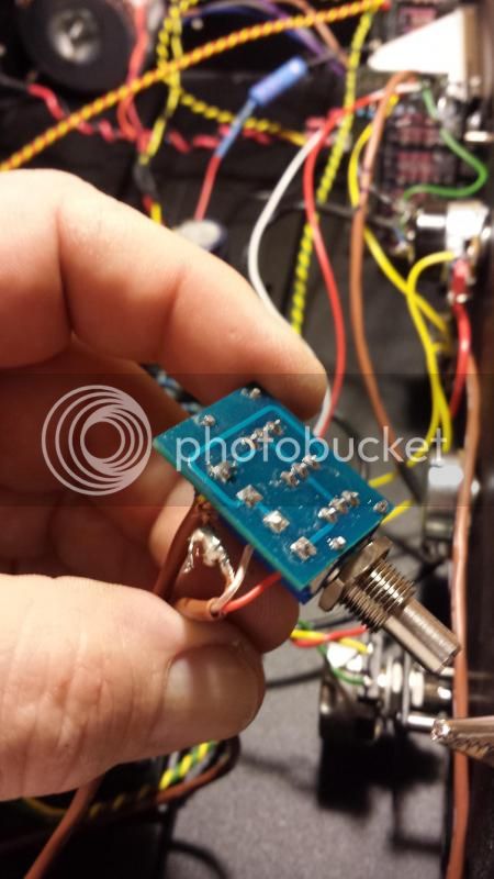
Pull the t-pad out of the case if it's bolted to the front and check your soldering there - if you can post a pic, it may help.
Ok, here are two pictures of the soldering on the L-pad, top and bottom.
I've checked continuity on the L-pad, no connection between the input and output "+" pads (regardless of position of rotation, CCW to CW), connectivity between the input and output "-" pads. I also checked between each "+" to "-" pad for continuity, found none.


![Soldering Iron Kit, 120W LED Digital Advanced Solder Iron Soldering Gun kit, 110V Welding Tools, Smart Temperature Control [356℉-932℉], Extra 5pcs Tips, Auto Sleep, Temp Calibration, Orange](https://m.media-amazon.com/images/I/51sFKu9SdeL._SL500_.jpg)


