[BUILD] 1176LN Rev D DIY

GroupDIY Audio Forum

Help Support GroupDIY Audio Forum:

This site may earn a commission from merchant affiliate links, including eBay, Amazon, and others.
mnats said:
Only if your time isn't worth much. But I suspect you command a decent hourly wage for the same time spent writing code. Given the time spent, are you really saving that much?

Well, the great thing about running your own startup company is that you get to work 10 times as hard for 10 times less money, so buying wasn't an option. Building was the only option. I sold off my store bought equipment and Waves Platinum to finance it, so there's a fixed kitty to do it on. And if any of them blew up, that would have been a loss of the store bought stuff and nothing to replace it.

If your offer to make one is genuine, I'm sure we will all be happy to pitch in and help if you post it when it is finished.

Absolutely. I'm pretty adept at Adobe Illustrator. It wouldn't be too hard to whip up a guide similar to Skylars but more up to date and for the rotary version.
 
One that I think is obvious, but maybe it's not is the Gnd on the meter board. In all the other stuff, you are warned not to hook up the other side of the shielded cable from Gnd/22. But it would appear in this newer board that you are supposed to hook it up, so I did. It would be nice to know that's correct before I commit to putting the meter board onto the POT and soldering it in, which I'm close to ready to do.
 
Dean Roddey said:
One that I think is obvious, but maybe it's not is the Gnd on the meter board. In all the other stuff, you are warned not to hook up the other side of the shielded cable from Gnd/22. But it would appear in this newer board that you are supposed to hook it up, so I did.
pad22_23.gif

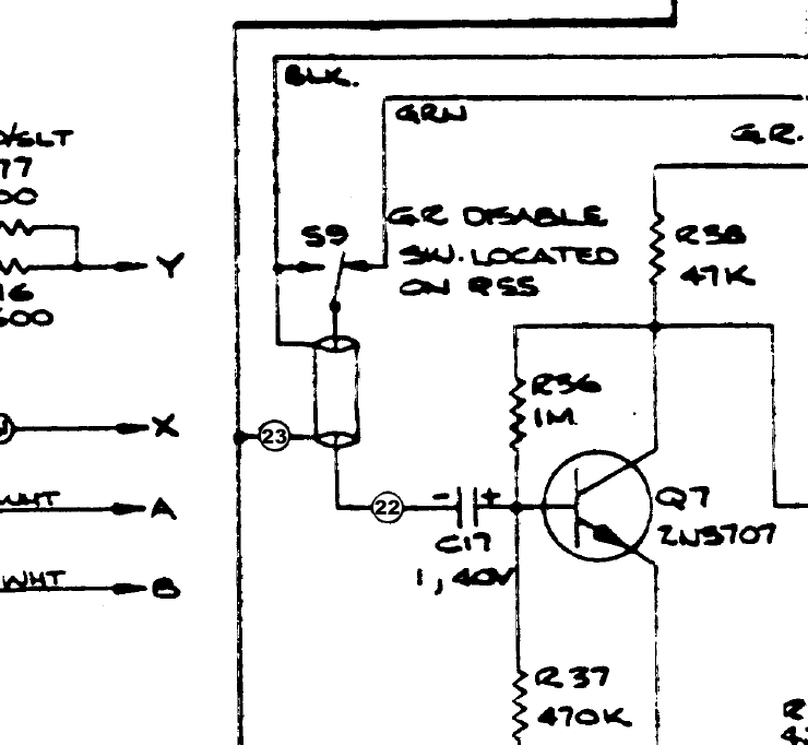
Look at the schematic above. Point 22 is the input to the gain reduction amplifier.

On the rotary meter boards the switch labeled S9 is incorporated into the rotary switch (on the original it is located on the attack potentiometer). In order to disable the gain reduction, the input of the gain reduction amplifier is shunted to ground, point 23 on the schematic. That thing that looks like a tube to the right of point 23 is the shield of the cable running to pad 22.

So yes, the shield connects to ground. Coincidentally, there is a ground pad right next to pad 22 on the main board.
Dean Roddey]It would be nice to know that's correct before I commit to putting the meter board onto the POT and soldering it in said:
Absolutely. I'm pretty adept at Adobe Illustrator. It wouldn't be too hard to whip up a guide similar to Skylars but more up to date and for the rotary version.
[/quote]
I'm going to hold you to that.
 
mnats said:
So yes, the shield connects to ground. Coincidentally, there is a ground pad right next to pad 22 on the main board.

I'm not doing the pins, I'm soldering them in, so just to make sure I grok what's going on... I can run one shielded between Gnd/22 on the main board to Gnd/22 on the meter board. Then 7 on the main board can be a single stranded to 7 on the meter board?


Please do not put the meter board onto a pot. The only thing on the board should be one resistor and a rotary switch.

That's what I meant, sorry. I'm about ready to commit to putting the board onto the rotary switch and solder it in.


I'm going to hold you to that.

No need to do that, I'll hold myself to it. I have no problem contributing back if I'm helped out. I've been encouraging people heavily on Gearslutz and the SONAR forum to get involved and answering lots of their questions about how hard these things are from the perspective of a non-electronics person and what all is involved and all that. I'm not just mooching here or anything. I'm actually getting a lot of people interested in it who wouldn't otherwise be, because they see someone like themselves able to do it.

http://www.gearslutz.com/board/good-news-channel/392034-woohoo-first-step-down-diy-path.html
http://forum.cakewalk.com/tm.asp?m=1728558

But I can pretty much guarantee you that most of them are interested in it only as a means to an end, i.e. to make better music, and not in the electronics for its own sake.
 
I have to agree with some of Deans points here.

Why would anyone risk their investment if they can get some form of affirmation or help from someone who knows more. I mean, once you cause a fault by an error in the way you have built your unit, it could end up costing you more in time trying to troubleshoot afterwards or you could give up hope fixing it and end up with an expensive paper weight.  :eek:

BTW, the pic was only to show that the Hairball T-Pad didn't require resistors as shown in one example.
 
[quote author=Dean Roddey]I'm not doing the pins, I'm soldering them in,[/quote]
I never mentioned anything about pins.
[quote author=Dean Roddey]...so just to make sure I grok what's going on... I can run one shielded between Gnd/22 on the main board to Gnd/22 on the meter board. [/quote]
Yes, there is a 22 and a ground on the meter and main board. The shield goes to ground and the 22 goes to the center conductor on each side of that cable.

If you left either ground (edit)unconnected there would be no path for the input of the gain reduction amplifier to connect to ground via the switch. In certain instances, this might cause interference to inject itself into the gain reduction amplifier causing spurious gain reduction where none is wanted.
[quote author=Dean Roddey]Then 7 on the main board can be a single stranded to 7 on the meter board?[/quote]
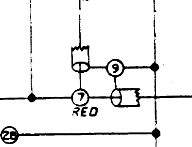
Armed with the knowledge I attempted to impart previously, look at this part of the schematic which represents the connection of point 7 to the main PCB:
point7_9.gif

The "tube" connected to point 9 represents the ______? (Hint: on the v2.2 boards there is a ground pad next to pad 7).

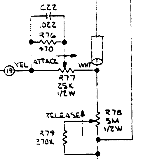
On the other side of this wire it connects to the attack pot as shown below:
point7_attack_pot.gif

Note that the tube is not connected to anything at this point, but that it does extend nearly to the attack pot clockwise lug. You can attach this wire to the rotary board which in turn connects to the pot.
[quote author=Dean Roddey]I'm actually getting a lot of people interested in it who wouldn't otherwise be, because they see someone like themselves able to do it.

http://www.gearslutz.com/board/good-news-channel/392034-woohoo-first-step-down-diy-path.html
http://forum.cakewalk.com/tm.asp?m=1728558

But I can pretty much guarantee you that most of them are interested in it only as a means to an end, i.e. to make better music, and not in the electronics for its own sake.[/quote]
As previously mentioned I'm not interested in selling more boards to people who have no interest in electronics. Those who aren't interested in electronics can stay at Gearslutz for all I care. My intention here is to have those drawings posted so that those that are not interested in electronics don't have to ask questions answered by the inscrutable schematic or that require valuable minutes of searching the forum to find the answers to ;D.
 
Dean Roddey said:
I don't get your point. De-soldering all the Molex connectors (more like 12 of them not a few, and they wouldn't have been easy at all because of their widely spaced multi-pin configurations and the fact that you can't get a vacuum to one side while heating on the other) wouldn't have solved anything because there'd have been no X/Y connector under them, nor should it be required because I have the numbered layout of the board in the PDF file, which already told me there's no X/Y connector on the board, which is why I asked.

My point is that you shouldn't be afraid to back track if need be.

And the last I checked, one of the best ways to learn is to ask someone who knows, because they've already done it. Geez...

Right, but if the answer involves you doing a bit of homework then I'd be inclined to point you back to where you came from.

I've spent 17 years to learning to make records, most of that time was spent reading and experimenting until I got the result that I wanted. It took about 15 years to figure out what the result that I wanted was.

I wish you good luck.

Mark
 
mnats said:
I never mentioned anything about pins.

I meantioned them, the point being that I'm soldering everything in, so I want to be sure before I do it. Once the board is soldered onto the rotary switch it's going to be a lot more of a PITA to change it.

Yes, there is a 22 and a ground on the meter and main board. The shield goes to ground and the 22 goes to the center conductor on each side of that cable.

I got that. That's already done.

If you left either ground connected there would be no path for the input of the gain reduction amplifier to connect to ground via the switch. In certain instances, this might cause interference to inject itself into the gain reduction amplifier causing spurious gain reduction where none is wanted.

Which 'either' are you referring to here?

Armed with the knowledge I attempted to impart previously, look at this part of the schematic which represents the connection of point 7 to the main PCB:

Sorry, but I have no idea what the answer is based on what you just said. There's one connector for 7 on each side, but in the rotary wiring guide it looks like you are really sharing a common ground between the two, as best I can tell. But clearly that's no longer applicable for the version I'm doing.

Given that there's only 1 connection for 7 on the meter board, and that 7 is nowhere near the ground connector on the main board, it wouldn't seem like you'd use a shielded cable, and what good would using a shielded cable be if neither side of the shield is connected? If one side should be connected, which side should it be? There's not another connection on the meter board to connect to.

And I'm not sure what the relevance of the attack pot is, since 7 is going to the board, not the attack pot.

There is a ground connector next to 7, but it's not covered by a Molex connector on my system or any that I've seen pictures of, so I didn't think it got used. Are you saying that the shield on the main board side should go to that non-molex'd ground connector?

As previously mentioned I'm not interested in selling more boards to people who have no interest in electronics. Those who aren't interested in electronics can stay at Gearslutz for all I care. My intention here is to have those drawings posted so that those that are not interested in electronics don't have to ask questions answered by the inscrutable schematic or that require valuable minutes of searching the forum to find the answers to ;D.

Well, I think that's a bad attitude, but it's yours to have if you want. Do you actually make music? If so, and you go to a place like Gearslutz and ask about ways to achieve some sound and someone just posts a link to a song that sounds like that and says if you can't figure it out from that, then maybe making music isn't for you, what kind of attitude would that be?

As ugly as it can get sometimes, Gearslutz folks are generally very happy to help newbies whose goal is to make music. I sat down last night and answered pretty extensively the 78123781491273'th post about recording levels in the digital world. I could have just said use the search, but that would have turned up a hundred threads, all of them basically arguments, which wouldn't have helped him at all really. He'd have been more confused after reading them than less.
 
jdbakker said:
Dean Roddey said:
But I can pretty much guarantee you that most of them are interested in it only as a means to an end, i.e. to make better music, and not in the electronics for its own sake.

Then maybe this isn't the place for them.

JDB.

It probably isn't, but the reason is not because of them.
 
I've spent 17 years to learning to make records, most of that time was spent reading and experimenting until I got the result that I wanted. It took about 15 years to figure out what the result that I wanted was.

That's my point though. I'm interested in MAKING MUSIC, not electronics. I'm perfectly happy to spend hours upon hours studying up on the subject of making music, or trying experiments, because that's what I want to do. And I'm a very technical guy, and I know how the equipment I use works and I understand the technology. But this 1176 is purely a tool for me. I have no interest in it in itself. I know perfectly well how to use it to make music, which is what is important to me. Hours and hours spent getting this figured out are hours I'm not using it to make music.
 
So, what I did, and I hope it's right, is the shield to the ground pad beside 7, red to 7, then red on the ratio board to 7.
 
So one question that no one really ever answered are the high voltage side of the power transformer. Do both of them need to be hooked up? It appears from others I've seen with the newer boards is that you connect up both dotted ones to L and both undotted ones to N, right? This one would seem to be very important to get right so as not to blow up something.

And, just as a side bar question... Why is there no fuse in this guy?
 
Dean Roddey said:
I've spent 17 years to learning to make records, most of that time was spent reading and experimenting until I got the result that I wanted. It took about 15 years to figure out what the result that I wanted was.

That's my point though. I'm interested in MAKING MUSIC, not electronics. I'm perfectly happy to spend hours upon hours studying up on the subject of making music, or trying experiments, because that's what I want to do. And I'm a very technical guy, and I know how the equipment I use works and I understand the technology. But this 1176 is purely a tool for me. I have no interest in it in itself. I know perfectly well how to use it to make music, which is what is important to me. Hours and hours spent getting this figured out are hours I'm not using it to make music.

You don't need a degree in electrical engineering to put together the 1176. Patience, common sense and making a few mistakes gets you most of the way there. Brow beating the collective brain trust of this group is not going to get you the result you desire, in fact it will serve only to deconstruct the community. I find this place a valuable resource, I'll be damned if I'll sit silent while someone attempts to school everyone on how it should be done.

If making music is your priority then I'd suggest buying an off the shelf product that suits your needs and start making music.

Mark
 
Dean Roddey said:
So one question that no one really ever answered are the high voltage side of the power transformer. Do both of them need to be hooked up? It appears from others I've seen with the newer boards is that you connect up both dotted ones to L and both undotted ones to N, right? This one would seem to be very important to get right so as not to blow up something.

And, just as a side bar question... Why is there no fuse in this guy?

F' me. SEARCH is your friend.

"power switch 1176" turned this guy up as the very first result.

http://www.groupdiy.com/index.php?topic=34039.msg416385#msg416385

"mains fuse 1176"

Turns this up

http://www.groupdiy.com/index.php?topic=646.msg199026#msg199026

Please do a search before posting.

A word of warning, with the kind of attitude your putting forward your gonna be on many ignore lists sooner than later.

Mark
 
I didn't ask HOW to do a fuse. I asked WHY doesn't it have a fuse. It's not the same question. You seem to be too busy trying to explain to me why I'm an moron than actually reading the question. And even if I found another thread, it's very difficult to know if the information is up to date with the latest designs, which is one of the big problems with how things are done around here.

Anyway, I will not be bothering you anymore. I'm not coming back because I really don't care to have anything to do with this kind of attitude. So you will not be forced to spend anymore of your time telling me what a moron I am.


If making music is your priority then I'd suggest buying an off the shelf product that suits your needs and start making music.

I already explained clearly why that wasn't an option, but you probably didn't read that post because there wasn't anyting in that one that you could sneer at.
 
Dean,

I think an important thing you're missing is that mnats' 1176 Project is not a commercial product.
When you buy his PCB, you're not buying support (manuals, tech support, email, etc) as with most commercial products.

This is why I think your comparison between mnats' PCB offering and your startup company is an apples »» oranges comparison.
You have a company, selling a software package to consumers, and part of that package is support for your product.
You've got a great support section right there on your website.
[off topic—your software looks really cool!]

Conversely, mnats is simply selling PCBs that have been verified to work if you build it properly.
He specifically states two things in his White Market thread that are relevant in this instance:

1:
IMPORTANT: Please note that the price above is for boards only. No individual technical or other support is included in the price. All the information offered is posted on my site and in the associated threads linked above.


2:
Please do not purchase these Rev A boards unless you are comfortable with reading schematics and are prepared to do some reading and to think for yourself!
I know he says "Rev A," but it should be obvious that he talking about all of his boards.

A prerequisite for building this unit is knowing how to read a schematic.

Furthermore, you really should know how to read schematics before you take on any project dealing with electricity.
If you don't know what you're doing, you could potentially kill yourself.
I know the current and voltages we're dealing with in this project are not nearly as dangerous as those in tube gear,
BUT you could easily burn down your house if you don't understand some core electrical concepts (like being able to understand a schematic).


If you were writing a guide on how to develop an automation software package like the one you've built, are you going to want to explain core concepts like variables, functions, data types, pointers, etc. ?
No—you're going to want to assume a basic level of C++ (or whatever language) familiarity and state the expectations you have of your end-users' skill level.

Here, mnats clearly states his expectations of the buyers' skill level.
He asks that you not buy his PCBs if you do not meet this level.

mnats offers a wealth of information on his website on how to wire one of these compressors.
Combine that with schematic-reading skills, and you have more than enough info to build an 1176 on your own.


Contrary to popular belief by new-comers, this forum is NOT about cheap & easy gear.


I am more than happy to offer my advice and help in any way I can.
The wiring guide I made was for myself while I was building this unit...
I've simply shared it here because I thought i might help some people.
It's not like anyone is trying to make some sort of definitive guide to 1176 building.
This project/thread is not an "1176 for Dummies" book.


Above all, though, I do not intend to offend or be-little anyone with this post.
If I have done so, I offer my most sincere apologies...just trying to help clarify things.
 
Skylar said:
Furthermore, you really should know how to read schematics before you take on any project dealing with electricity.
If you don't know what you're doing, you could potentially kill yourself.
I know the current and voltages we're dealing with in this project are not nearly as dangerous as those in tube gear,
BUT you could easily burn down your house if you don't understand some core electrical concepts (like being able to understand a schematic).

Skylar,

Thank you for your post.  You have (once again) hit the nail on the head.

I've been following this thread a little and have some pretty strong feelings.  Unfortunately, things are so busy with my day job right now that I haven't had the time to write a thoughtful response.  Skylar's entire post pretty much sums up my feelings.

The part quoted above it really important.  We're not knitting sweaters here.  If you mess something up, it's not an issue of one sleeve being longer than the other.  It's a serious safety issue.

I think having basic schematic reading skills and a grasp of basic electronic concepts is a must.  I also think these basic skills are a must for any musician or producer.  Having these basic skills will be invaluable in the studio or on tour when a piece of gear decides to stop working.

Taking a few hours to read up on these things will go a long way.

Thanks,

Mike

 
Dean Roddey said:
mnats said:
I never mentioned anything about pins.

I meantioned them, the point being that I'm soldering everything in, so I want to be sure before I do it. Once the board is soldered onto the rotary switch it's going to be a lot more of a PITA to change it.

The switch can only go in one way (well, four really, but each way operates identically). Don't worry about soldering it in. I suppose it could also go on the wrong side of the board, but it would be very difficult to get the solder to flow as the pads are only on one side.

[quote author=Dean Roddey][quote author=mnats]If you left either ground connected there would be no path for the input of the gain reduction amplifier to connect to ground via the switch. In certain instances, this might cause interference to inject itself into the gain reduction amplifier causing spurious gain reduction where none is wanted.[/quote]

Which 'either' are you referring to here?[/quote]

My apologies, I meant to write unconnected. I've corrected my post above.

[quote author=Dean Roddey][quote author=mnats]Armed with the knowledge I attempted to impart previously, look at this part of the schematic which represents the connection of point 7 to the main PCB:[/quote]

Sorry, but I have no idea what the answer is based on what you just said.[/quote]

Sorry, I was trying to 'teach you to fish', but now I see that you are truly sincere in your desire to learn nothing about electronics.

You use a shielded wire here and connect the shield to the ground on the main board only.

[quote author=Dean Roddey]
Given that there's only 1 connection for 7 on the meter board, and that 7 is nowhere near the ground connector on the main board...[/quote]

[quote author=Dean Roddey]
There is a ground connector next to 7, but it's not covered by a Molex connector on my system or any that I've seen pictures of, so I didn't think it got used. Are you saying that the shield on the main board side should go to that non-molex'd ground connector?[/quote]

The board you have does or does not have a ground connection next to pad 7?

If it does not you have a version earlier that v2.2, and you can scrape back a bit of the top ground plane to make the connection.

[quote author=Dean Roddey]And I'm not sure what the relevance of the attack pot is, since 7 is going to the board, not the attack pot. [/quote]

Yes, as I previously stated: "You can attach this wire to the rotary board which in turn connects to the pot." It is a bit circuitous, but "easier" for you.

[quote author=Dean Roddey][quote author=mnats]As previously mentioned I'm not interested in selling more boards to people who have no interest in electronics. Those who aren't interested in electronics can stay at Gearslutz for all I care. My intention here is to have those drawings posted so that those that are not interested in electronics don't have to ask questions answered by the inscrutable schematic or that require valuable minutes of searching the forum to find the answers to ;D.[/quote]

Well, I think that's a bad attitude, but it's yours to have if you want. Do you actually make music? If so, and you go to a place like Gearslutz and ask about ways to achieve some sound and someone just posts a link to a song that sounds like that and says if you can't figure it out from that, then maybe making music isn't for you, what kind of attitude would that be?[/quote]

That's very generous of you to permit me to have my opinion. Thanks for that.

These days I find time to play my bass and piano, but seldom record.

If you are comparing my boards to someone linking to a song, well I disagree with that comparison. In that context someone who has my boards would be like someone having access to the multitrack session with recalls who just has to figure out how to load it into Pro Tools.

90% of the "wiring" has been done with these boards. All that is required is to hook it up to the off-board components and perform the calibrations.

[quote author=Dean Roddey]I didn't ask HOW to do a fuse. I asked WHY doesn't it have a fuse. It's not the same question. You seem to be too busy trying to explain to me why I'm an moron than actually reading the question. And even if I found another thread, it's very difficult to know if the information is up to date with the latest designs, which is one of the big problems with how things are done around here.[/quote]

I think you will find that many power transformers have a built in thermal fuse and have had them for at least the life of this project.

[quote author=Dean Roddey]Anyway, I will not be bothering you anymore. I'm not coming back because I really don't care to have anything to do with this kind of attitude. So you will not be forced to spend anymore of your time telling me what a moron I am.[/quote]

What about that drawing you were going to do?
 
+1 Skylar, Mike and Mako

The last page or two just confirms my feeling more and more nowadays: more and more people wanting something for nothing. They can't afford the real product so they try to get around it and save a few $$$ and then when trouble hits them and they're too lazy and/or ignorant to figure it out, they expect someone to come in there for free and fix it for them.

My take is that it's cool if someone's willing to offer the help, that's fine. But somehow people expect it, like they're entitled to it (I'm talking about this situation as touched on by Skylar above). That blows me away.

So, like everyone else's opinion, that's mine. If someone has a problem with it, as they say in the old world, "tough shitski".
 

Latest posts

Back
Top