[BUILD] 1176LN Rev D DIY

GroupDIY Audio Forum

Help Support GroupDIY Audio Forum:

This site may earn a commission from merchant affiliate links, including eBay, Amazon, and others.
I would like to help but seriously I know less than you.  :-\

I can see that you're passionate about completing your build and getting it working and at the same time, trying to spread a good word about the unit.

I only have pics to offer from what I have gathered but Il try to throw in what I have learnt so far.
 
I found the problem: The R32 that I replaced had cold solder, but was a tricky one! It did not appear to be cold solder at all!
I rarely have cold solder in my small diy´s but we are always learning!

Thank you all for you help.
luis
luis said:
Echo North said:
....

Luis:
I doubt it's damaged. Lots of people have accidentally wired the OT wrong and had R32 flame up (including me!).  

Mike

Well, my compressor passed sound before, the meter moved (when I had the OT correctly wired) and now after burning the  R32 due to ot wired wrong , the sound does not pass neither the meter moves.
I already unsolder all transistors, and will try again with new transistors. My doubts:

- even with the transistores damaged should the sound pass?
Can the wrong OT wiring damage other components beside R32?

Thanks
 
luis said:
I found the problem: The R32 that I replaced had cold solder, but was a tricky one! It did not appear to be cold solder at all!
I rarely have cold solder in my small diy´s but we are always learning!

Thank you all for you help.

Awesome.  I know how rewarding it is to finally find a pesky problem like that.

Happy squishing!

Mike
 
What about that drawing you were going to do?

Yes, I will still do it, though I don't know why I should, given the comments being made by some others here. But I'm willing to do it to help others coming after me.

So it powered up fine, well after the frying of R32 the first time. It would be awfully nice if you'd take a minute and update the incorrect output transformer labels on the board drawing in the PDF file, so that people could avoid this after having covered the board with the molex connectors and wiring it up based on the PDF file.

So anyway, I replaced R32 and figured out the correct output transformer wiring, and it powers up. The only wierdness so far is that the meter lamp doesn't go off when the meter switch is in the first position. The meter reacts as probably expected pre-calibration and goes hard right in position two (GR I assume) and drops back the other direction in position three (output level I assume.) But the meter lamp doesn't go off in position one. I have it strapped across the +/- of the power transformer inputs to the main board with the appropirate 220 2W resistor.

I'm going to go ahead with the calibration, but I'm guessing that the meter not going off is not a particularly good sign. But I'll see how it calibrates. I figured out after the fact what the shorting pads were for. I didn't have any header to go there so I just made my own out of spare legs cut off some larger capacitors in an earlier project. So I should be able to give the calibration a try and see what it does in the meantime.
 
fazeka said:
+1 Skylar, Mike and Mako

The last page or two just confirms my feeling more and more nowadays: more and more people wanting something for nothing. They can't afford the real product so they try to get around it and save a few $$$ and then when trouble hits them and they're too lazy and/or ignorant to figure it out, they expect someone to come in there for free and fix it for them.

My take is that it's cool if someone's willing to offer the help, that's fine. But somehow people expect it, like they're entitled to it (I'm talking about this situation as touched on by Skylar above). That blows me away.

So, like everyone else's opinion, that's mine. If someone has a problem with it, as they say in the old world, "tough shitski".

Well, unlike you guys, I'm GLAD to give people help. And once I know how it works I'll be glad to help people all the time. I do this on the music related fora all the time and put in a lot of time helping other people. You know nothing about me and trying to act like I'm some greedy bitch who just wants to get everything handed to him is ridiculous. I'm an extremely helpful person in those areas where I have the expertise. But this is an area where I need help in this case. I'm perfectly happy to do the footwork to measure things and figure out what's going on, but I cannot figure out how to do those things myself.

And yes, gasp, I'm freaking poor so I have to build things instead of buy them. I mean how sick is that? I should shoot myself or something, obviously.
 
Dean Roddey said:
So it powered up fine, well after the frying of R32 the first time. It would be awfully nice if you'd take a minute and update the incorrect output transformer labels on the board drawing in the PDF file, so that people could avoid this after having covered the board with the molex connectors and wiring it up based on the PDF file.

It has been updated.

http://www.geocities.com/m_natsume/1176_revision_d

See the top two links?  He has a .pdf for V1 and V2.  Keep in mind some people purchase boards and sit on them for a while so there maybe some people who still need to access the V1 .pdf.

Dean Roddey said:
So anyway, I replaced R32 and figured out the correct output transformer wiring, and it powers up. The only wierdness so far is that the meter lamp doesn't go off when the meter switch is in the first position. The meter reacts as probably expected pre-calibration and goes hard right in position two (GR I assume) and drops back the other direction in position three (output level I assume.) But the meter lamp doesn't go off in position one. I have it strapped across the +/- of the power transformer inputs to the main board with the appropirate 220 2W resistor.

I don't know the rotary version very well.  I assume the 3 pos are bypass/GR/+4.  If that is the case it would be right that your lamp stays on in bypass.

Where is the "off" on that rotary or separate?

Mike
 
I was told that off is the first position of the meter switch. So I assume there's no bypass, just off, GR, and output level? There's only three positions and one of them is supposed to be off, so that only would leave two others.

See the top two links?  He has a .pdf for V1 and V2.  Keep in mind some people purchase boards and sit on them for a while so there maybe some people who still need to access the V1 .pdf.

Hmmm... The one I have on my computer has the right info, but the one I printed out much earlier must have been the earlier version or something that still had the incorrect info.

Oh well, that's spilt milk under the bridge now I guess. As long as it's been corrected for those folks smart enough to print out the correct one.
 
I really think the 3 pos are bypass/GR/+4 looking at a few complete units online.

Is your toroid primary wired to the meter board?  If you wired the toroid primary directly to your IEC inlet w/ no switch in between you have no off switch.

Sounds like it's working right.

Mike
 
OK, I guess whoever told me that earlier misunderstood what I was asking. . There are so few folks with pictures of rotary versions to look at as sanity checks that I didn't question that answer. It was back earlier in this thread somewhere.

Oh well, I'll add a power switch to it. But, that's a good thing, since it means it's not hosed (in that way anyway, still plenty of ways to screw the pooch yet I'm sure.)
 
If you want to add a switch (which you don't have too) you would just switch the live on your primary side.  Or your L and N if you want to be safer and have a DPDT switch.

I think you are ready for calibration.

Mike
 
Oh, so it has to be on the high voltage side? I didn't think about that, but I guess it wouldn't cut off the juice from the wall if you did a DPDT on the other side of the transformer, eh? It's kind of a bummer since it's going to mean running those high AC voltages all the way to the front of the thing and back, across all those wires. That's not a potential hum problem or anything?

Though, I could actually put the switch on the back easily enough. Where it will be in the rack it's easy enough to get to on the back.

So what amperage should the switch handle?
 
Something rated for 125V/1A or better. 

If you run it to the front you'll want to keep it way from the audio as much as possible.

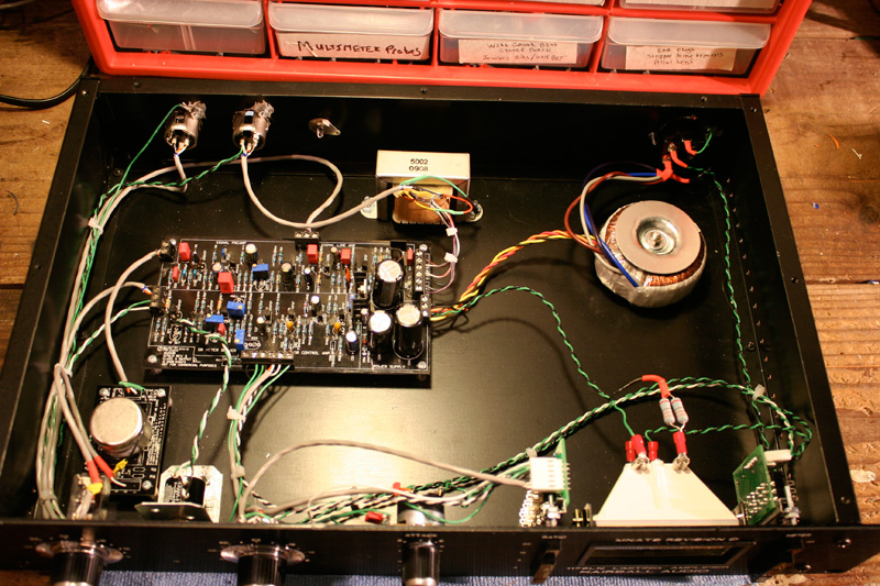
Here is what I do:
3205487836_14926b7e4e_o.jpg


Notice how I keep the power switch wires far right (green/black twisted on the right).

Mike
 
I have some spare SP switches from the LA-2A, which are 3A 125V, so they should be plenty. Unfortunately for me there's no way to get the power to the front without crossing way too many audio connections. I didn't account for the need for an audio switch, so all the knobs are well spaced out in a single line along the front panel. So there's no space to put a switch other than slap in the middle of the front panel now.

I'll just it on the back.
 
Dean,

The factory has been bringing the AC up to the front since S/N: 00000001. Just make sure to twist the wires fairly good along the way. (looks like Mike filled you in)

Because of my I/C background I don't like green used for power period, but because this is DIY it's an non issue. (if it was used)  Be careful twisting the wires on the transformers, they can twist off rendering the transformer useless without repair or replacement depending on damage. Twisting of the power wires and keeping them far away from signals has been discussed before. Best thing to do is study the STA-Level wiring and do like that and you should have no problems in your builds


Also if you must switch one side, take the line voltage (black. hot) as the switched side, but as discussed before it's best to do both.

Kaz
 
Everything is very well twisted or shielded. But it would be awkward from an aesthestic POV to try to wedge a power switch up front now with the way I've spread everything out.

I'll make another run to Fryes right now and get a DPDT switch and do it right. That's only three runs to Fryes today, which is actually not so bad an average for my 'last day of a project' type days.
 
Dean Roddey said:
Well, unlike you guys, I'm GLAD to give people help. And once I know how it works I'll be glad to help people all the time. I do this on the music related fora all the time and put in a lot of time helping other people. You know nothing about me and trying to act like I'm some greedy bitch who just wants to get everything handed to him is ridiculous. I'm an extremely helpful person in those areas where I have the expertise. But this is an area where I need help in this case. I'm perfectly happy to do the footwork to measure things and figure out what's going on, but I cannot figure out how to do those things myself.

And yes, gasp, I'm freaking poor so I have to build things instead of buy them. I mean how sick is that? I should shoot myself or something, obviously.

Nah, I think you've missed my point and you're not going to get it. That's OK.

It's good to see you're starting to work through the problems on your unit.
 
No, I think I understand all your points. You guys think that electronics knowledge is something worth having in and of itself and you shouldn't build things you don't understand. I have no problem with getting a little electronics knowledge and I have during this process (this is my fifth project, and the last until I can sell a kidney or something to finance some more.) But I have huge intellectual commitments in other areas, and there's only so much I can do. I'll be happy to help some of you if you need some software help, since I suck at a lot of things but that's not one. It's just not worth my digging in deep for something that I'll likely not do again for a long time. I'll have completely forgotten it by the time I need it again and will have to do it all over anyway.

And I will be making what I think will be a huge contribution here in the form of a diagram that anyone like me should be able to use to build the rotary version of this thing without worries. So I'm going to give back in return for some help.

Anyway, I now I have a power switch. I'm going to get my Karma together for a bit here while it warms up and then do the calibration and see what happens.
 
Echo North said:
Something rated for 125V/1A or better. 

If you run it to the front you'll want to keep it way from the audio as much as possible.

Here is what I do:
3205487836_14926b7e4e_o.jpg


Notice how I keep the power switch wires far right (green/black twisted on the right).

Mike
Mike whats that gadget you have in between the Large Input and Output knobs inside your case? It's where the hole on Purusha's case is and I could never figure out what the purpose of the hole and mounts were. I was going to put a led light in there to show that the machine is on or off.
 
That is r71 the 0 adjust.

You can use a PCB mount trimmer, but I like to put a pot on the front panel like an original.  Since the 1176 can drift a little it's nice to have the 0 adjust accessible through the front panel.

I used a 10 turn pot but a single 2K linear would work fine.

Mike
 
Echo North said:
That is r71 the 0 adjust.

You can use a PCB mount trimmer, but I like to put a pot on the front panel like an original.  Since the 1176 can drift a little it's nice to have the 0 adjust accessible through the front panel.

I used a 10 turn pot but a single 2K linear would work fine.

Mike

My meter drifts based on the voltage coming out of the mains that day.

I never bother to adjust it because it would be a daily or even hourly event. :)

Mark
 
Back
Top