[BUILD] 1176LN Rev D DIY

GroupDIY Audio Forum

Help Support GroupDIY Audio Forum:

This site may earn a commission from merchant affiliate links, including eBay, Amazon, and others.
canidoit said:
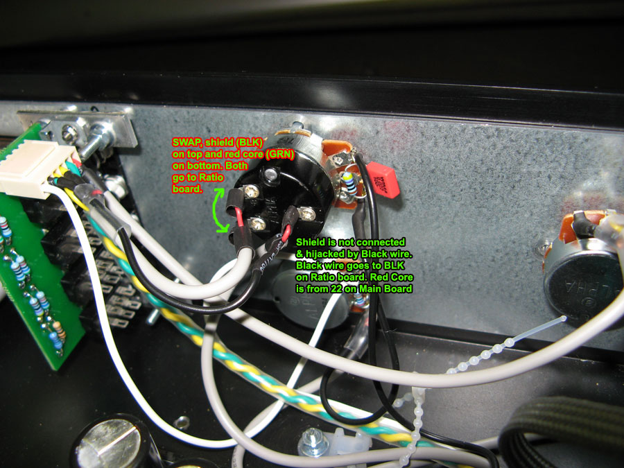
Here is the correction to the wiring. Thanks for telling me to do a continuity check  :)

wireCheck2b.jpg

Swapping the wires is what I did too! but I extract the shield, that I previously cut from the pad 22's wire and reconnected to the lug! It's the same as you did!
How's your unit behavior now? mine is pretty fine!

Cheers,

Eddie  ;D
 
Eddie, I am not up to that stage yet. I still have to do my Meter board wiring and XLR output and output Xformer wiring. I added a ground lift to the XLR ins and outs. I am not sure yet whether I will implement the Drips ground lift system using a cap and resistor or just leave it as a dead connection for ground lift on. Anyone implemented ground lift in their 1176 Rev D, if so, what worked for them?
 
canidoit said:
Eddie, I am not up to that stage yet. I still have to do my Meter board wiring and XLR output and output Xformer wiring. I added a ground lift to the XLR ins and outs. I am not sure yet whether I will implement the Drips ground lift system using a cap and resistor or just leave it as a dead connection for ground lift on. Anyone implemented ground lift in their 1176 Rev D, if so, what worked for them?

Ok! I implement a ground lift in one of my 1176, but you know what... it is dead quiet both ways... never get problems with noise floor! but is a good idea that Drip's connection... I think you can use that!

one thing I think it was discussed previously in this thread is a stereo link for the Rev D... we can't just add a wire like in the mnta's Rev J... I saw the Purple audio schematic from the MC77 (that is a Rev D class A) and they have a circuit regarding the stereo connection... i think that should be great for improve this project...

MC77 Manual & Schematic Pdf File

Just see the last page to view the stereo link schematic.
Any Idea about how to wire that?

Hey Canidoit, when you get yours stuffed and working, please let me know if everything's ok!

Cheers,

Eddie  ;D

 
SaMpLeGoD said:
canidoit said:
Eddie, I am not up to that stage yet. I still have to do my Meter board wiring and XLR output and output Xformer wiring. I added a ground lift to the XLR ins and outs. I am not sure yet whether I will implement the Drips ground lift system using a cap and resistor or just leave it as a dead connection for ground lift on. Anyone implemented ground lift in their 1176 Rev D, if so, what worked for them?

Ok! I implement a ground lift in one of my 1176, but you know what... it is dead quiet both ways... never get problems with noise floor! but is a good idea that Drip's connection... I think you can use that!

one thing I think it was discussed previously in this thread is a stereo link for the Rev D... we can't just add a wire like in the mnta's Rev J... I saw the Purple audio schematic from the MC77 (that is a Rev D class A) and they have a circuit regarding the stereo connection... i think that should be great for improve this project...

MC77 Manual & Schematic Pdf File

Just see the last page to view the stereo link schematic.
Any Idea about how to wire that?

Hey Canidoit, when you get yours stuffed and working, please let me know if everything's ok!

Cheers,

Eddie  ;D
No idea Eddie how to wire that, sorry. :(
It be great if there was a PCB board floating around to add stereo link.  :)
 
What fuse for the IEC socket? On the UA 1176 re-issue, they use I think a 250 volts 1/16 amp fuse Slo Blo. What is it for the Mnats 1176 Rev D using Hairball Power Transformer for 240 volts?

For those that know the 1176 Mnats Rev D very well, can you please have a look at my visual check thread which I have placed up,
http://www.groupdiy.com/index.php?topic=34385.0

Can you spot anything wrong visually with my build.

It would be great  :)

Thanks
 
Any advise before I plug it in and turn it on. Any pre-liminary test procedures I should be aware of and implement before turning it on?
 
canidoit said:
What fuse for the IEC socket? On the UA 1176 re-issue, they use I think a 250 volts 1/16 amp fuse Slo Blo. What is it for the Mnats 1176 Rev D using Hairball Power Transformer for 240 volts?

http://www.groupdiy.com/index.php?topic=47.msg420494#msg420494

Mark
 
Biasrocks said:
canidoit said:
What fuse for the IEC socket? On the UA 1176 re-issue, they use I think a 250 volts 1/16 amp fuse Slo Blo. What is it for the Mnats 1176 Rev D using Hairball Power Transformer for 240 volts?

http://www.groupdiy.com/index.php?topic=47.msg420494#msg420494

Mark
Looking at that link:
Assuming, you use a 6VA transformer, divide this VA by your mains voltage, giving 6VA/110V=0.055A. This transformer is maybe only 70% efficient, so multiply the 0.055A by (1/0.7), giving 0.078A. Nearest larger fuse rating will be 100mA. For the larger inrush current of a toroid you want this with slow blow/time lag characteristic. Fuse voltage rating is at least your mains voltage to prevent arcing when this fuse blows, so a 250V/100mA T (=slow blow) might fit for this example. Your transformer may/will be different, so do the math with your values.


Hairball's power transformer specs:
TRANSFORMER, 30VA, 2 X 25V
Voltages, primary:0-115, 0-115
Voltages, secondary:0-25, 0-25
Power, per secondary winding:15VA
Approval Bodies:EN60950, EN60742, UL Recognised
Current rating:0.6A
Diameter, bolt hole:5mm
Diameter, RoHS Compliant: Yes

That would mean Hairballs power transformer is 30VA. So using that method, 30va/240v = 0.125.
0.125 X 1/0.7 = 0.178A

That would mean the closest larger fuse rating would be 200ma fuse at 250 volts that I should install? Have I done this right?
 
Is there a calibration process for the Distortion trimmer R86? I was playing around with it, I want to set it to standard, but I can't find any info on this?
 
canidoit said:
Is there a calibration process for the Distortion trimmer R86? I was playing around with it, I want to set it to standard, but I can't find any info on this?

http://www.groupdiy.com/index.php?topic=34385.msg420877#msg420877

 
Hi all,

I am having some difficulty calibrating my 1176 rev. D for 10 dB of limiting. I triple-checked my wiring and can't see anything wrong. I did the Q-bias adjustment and NULL 0.00 VDC pot adjustment.

When I try to set my 10dB swing, I can only get a max of +8.75 dB with the input attenuator full up (full CW). It's funny, my output is barely up (almost full CCW at -46 dB) to get the 0 dB. Not sure if those two are interacting, but I tried turning up the Output to get +10 dB but this throws the swing out of whack and then I have to start over.

Something else I've noticed...

Is it normal for the VU meter to peg when in VU/+4 mode and output at full CCW? I have to turn the Output past -54 dB to get the VU needle back to the left... it's like the Output pot is shorted (?) in the lower range?

(I am using an Alpha output pot, for what it's worth)

Best,
Chris
 
fazeka said:
Hi all,

I am having some difficulty calibrating my 1176 rev. D for 10 dB of limiting. I triple-checked my wiring and can't see anything wrong. I did the Q-bias adjustment and NULL 0.00 VDC pot adjustment.

When I try to set my 10dB swing, I can only get a max of +8.75 dB with the input attenuator full up (full CW). It's funny, my output is barely up (almost full CCW at -46 dB) to get the 0 dB. Not sure if those two are interacting, but I tried turning up the Output to get +10 dB but this throws the swing out of whack and then I have to start over.

Something else I've noticed...

Is it normal for the VU meter to peg when in VU/+4 mode and output at full CCW? I have to turn the Output past -54 dB to get the VU needle back to the left... it's like the Output pot is shorted (?) in the lower range?

(I am using an Alpha output pot, for what it's worth)

Best,
Chris
Are you talking about the calibration in the UREI manual for -10 which is for the R44 trimmer. If so, I had the same problem. I couldn't get gain reduction to meter properly when compressing.

I solved it by putting R44 in circuit(install jumper), leaving the Attack off, Meter on +4 and turned R44 trimmer till I could move the VU needle to 0. If the VU needle wasnt moving or couldnt get the VU needle close to 0, I used a combination of Zero adjustment and R44 trimmer to move the needle to 0. Once the VU needle was set to 0, I put a signal thru the unit, turn attack on and the needle was moving in Gain Reduction finally.
 
I have a question reguarding setting the Q Bias.

In Mnats video he reffers to placing it closest to ground (In the animated video the link moves on ground side of the pot).

Not sure what is ment by this. Does it meas to adjust the Q bias trim pot to lowest value?  ???
 
rrs said:
I have a question reguarding setting the Q Bias.

In Mnats video he reffers to placing it closest to ground (In the animated video the link moves on ground side of the pot).

Not sure what is ment by this. Does it meas to adjust the Q bias trim pot to lowest value?  ???

That is the starting position for your adjustment.

When you make the adjustment you are turning the wiper away from ground until you get a drop of 1db which is slightly into conduction.

Mike
 
Actually for a JFET it's the other way around, the closer to 0V Vgs is, the higher the current Ids will be, so the more negative Vgs is the closer to pinchoff (ie no conduction) it gets.
 
Echo North said:
rrs said:
I have a question reguarding setting the Q Bias.

In Mnats video he reffers to placing it closest to ground (In the animated video the link moves on ground side of the pot).

Not sure what is ment by this. Does it meas to adjust the Q bias trim pot to lowest value?  ???

That is the starting position for your adjustment.

When you make the adjustment you are turning the wiper away from ground until you get a drop of 1db which is slightly into conduction.

Mike

Thanks but I'm still no clearer as to how to perform this process. I am gathering I need to adjust the trimpot (R59) to measure 0V somewhere? Maybe at pin 18 ??
Am I on the right track?
 
rrs said:
Echo North said:
rrs said:
I have a question reguarding setting the Q Bias.

In Mnats video he reffers to placing it closest to ground (In the animated video the link moves on ground side of the pot).

Not sure what is ment by this. Does it meas to adjust the Q bias trim pot to lowest value?  ???

That is the starting position for your adjustment.

When you make the adjustment you are turning the wiper away from ground until you get a drop of 1db which is slightly into conduction.

Mike

Thanks but I'm still no clearer as to how to perform this process. I am gathering I need to adjust the trimpot (R59) to measure 0V somewhere? Maybe at pin 18 ??
Am I on the right track?
David, I thought the voltage measurement was only needed if you are adjusting the null trimmers? You measure the voltage at one of the resistors and set the null and zero trimmers to get zero voltage at the resistor (can't remember which resistor but it's in the video).

As for the q-bias, I just kept on turning it until I was able to see the VU move from what I recall. At the start it wasn't moving because the trimmers were very far off calibration so I kept turning it CW and CCW till I got movement.
 
After Buildt my 3rd 1176LN, I was wondering about a Stereo interconnect... I just looking at to the MC77 schematic, but it's a little bit confuse for me... what they mean as "loop Relay"??
Please see HERE (at page 15)
The sytereo interconnect, as I notice, is NOT like just wiring a wire like in the Rev J! maybe I'm wrong, but I think I'm not  :-\
We should get the 1176SA inbox each unot too, just leaving outside the adjust pot... or if we need to made some extra board to do the stereo link, we could "insert" this little schematic on the board, right?
I love to be able to get my 1176 Rev D stereo connected!
Can anyone help with this?
Cheers,

Eddie :)
 

Latest posts

Back
Top