[BUILD] 1176LN Rev D DIY

GroupDIY Audio Forum

Help Support GroupDIY Audio Forum:

This site may earn a commission from merchant affiliate links, including eBay, Amazon, and others.
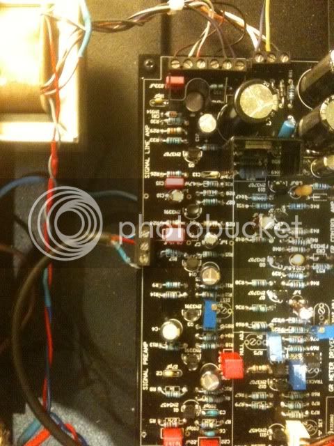
I'm using Alpha pots. They all seem to work properly on both units. As is said, both units were working perfectly until I re-openend the case and tightened the pot screws. I haven't changed anything else. I checked all the wires, but can't see anything wrong here.

I can do the whole calibration and also pass a signal trough the units. Meters in VU mode work as they should, but that's it. No audible and visible  GR anymore. In GR Mode the meter just sets to zero and does not move any more.

Shouldn't I notice any problems during the calibration if I have faulty wireing?

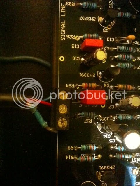
Or could it probably be a ground issue? I'm not sure if the metal housings of all the pots had made electrical contact with the front plate before I tighend the screws. Now they definitly do.
 
Are you using a oscilloscope to check the waveform from the output? check if the PAD 22 of the main PCB is connecting to ground... if yes you have somehow the GR disabled. Are you using the attack pot with switch? are this wiring ok?
Once I had a problem like that and notice that the bolt that was attaching the switch set to the case was contacting with the back of the ratio's board, so I didn't have GR too... once I realize that, put some isolation on it, and all goes right!
Cheers,

Eddie
 
I have an oscilloscope, but I haven't used it yet to check the waveform at the output. The attack pot switch works fine. I can measure 0 ohm between pad 22 and ground when its turned to the "off" position and 124k ohm when its turnend on.
 
Calibrating:

I readed the original Urei calibration guide again, and they say, you should give a signal 0dB = 0.775 V to the input, and set the input and output pots in a position to get  +4dB on the output. I think, they means dBu, and if you now calibrate your VU meter bias to "0" , it makes sense for me to get the right levels and meter parameters through the unit.....

0 dBu should be -18dbfs, if you got an AD Converter, that works on +4 dBu. I got a RME Fireface, and it seems to should be so. Today I wanna proof the levels on the FF using my friends oscilloscop and this useful calculator: http://www.sengpielaudio.com/calculator-db-volt.htm

Noise:
I calibrated my unit before, and measured the SN RAtio. If I turn the output put CCW, all seems right, but if I turn in to CCW, I got a noise , coming from the input stage, that sounds like pink noise with some modulation........ The SN RAtio with this noise is appromimitatly @ -62 dB, Urei got an SN Ratio @ 81 db ..... (I turned GR off @ all measurements)

Any ideas, where the noise is come from ? Change the FETS ???? I could upload an audio file to let you hear this noise .........

best thanks for your ideas and your friedly help

kindly regards.

Jens

Could be anybody so friendly and generious to tell me the voltages of the connections of the FETS Q1 and Q2 ?

 
Both units finally started to work again. Strangest thing I ever had. I did nothing, just went to my bed. In the morning, everything was fine again...

One last topic. Both units seem to create hum when the meter switch is set to +4 and +8. No hum when its set on GR. I moved the wirering around and as far away from the toroid as possible, but nothing changes.

What signal to noise ration am I supposed to have ?
 
Majestic12 said:
What signal to noise ration am I supposed to have ?

The Manual of the original says around 81dB at thereshold limiting...
Did you check your ground connection?
Try to connect the secondarie's CT of the power transformer to the star ground if you don't.
Cheers

Eddie
 
I just finished my Rev D and I must say:
Thank you Echo North and Mnats for all the work you've put into this. Thanks Mike for the sending of the input xfmr pcb (at no cost!)
Excellent stuff, wiring pages on Mnats site are also freaking brilliant.

My first DIY project in recording audio and this thing rocks. When set to squash it poops out waveform bricks :)


Im saving up for my next project!
 
Another 1176 rev D has seen the light of day!  ;D
Again, big thanks to Mako for this great project, to Mike for the wonderful cases and to Ed for the fantastic transformers. THANKS GUYS!!!

Henrik
 
MY first two units are ready now, and they seem to work like they should do. The only exception is, that R86 100 Ohm trim in both units has no exercise control to the quality of the output signal and the THD Distortion can not change with this trim pot.
I tryed a lot of variations of the input signal, nothing happens on the output .
I had a look with a spectrum analyser to the output, I can see the signal and the first and second harmonic, R86 has no control too to this.......
When I have a look to the schematic, thats no surprising with the big R15 6,8K in this way.


If anyone has experiences or practical knowledges to fit this, It would be nice, to let me hear your ideas.

Thanks for an small reply.

Best regards

Jens
 
Hi guys,
I don't understand what's happened with GR but I can't do the calibration !! if I get out of this cable( Ground) GR is working  ??? :) If I plug it no GR !
any idea ?
Thanks

-1-1.jpg


-2-1.jpg


jandoste said:
Hi guys,
I don't understand what's happened with GR but I can't do the calibration !! if I get out of this cable( Ground) GR is working  ??? :) If I plug it no GR !
any idea ?
Thanks

Are you sure you didn't reverse the wires on the output pot? this unconnected cable is just ground... if you reversed the cable at the out pot your sending ground to pad 15 at ratio board, not the signal...
Cheers

Eddie.
 
SaMpLeGoD said:
jandoste said:
Hi guys,
I don't understand what's happened with GR but I can't do the calibration !! if I get out of this cable( Ground) GR is working  ??? :) If I plug it no GR !
any idea ?
Thanks

Are you sure you didn't reverse the wires on the output pot? this unconnected cable is just ground... if you reversed the cable at the out pot your sending ground to pad 15 at ratio board, not the signal...
Cheers

Eddie.

Thanks Ediee,
I cheched  twice and you're right :)
Cheers,
 
Hey Guys,

I'm looking which rev to build... now, in the BOM for Rev D, there are some parts that I didn't find or where I have some questions about.

- Some Caps are listed with "elec or film"...what do you recommend? Advantages? Perhaps sonically?
- The Mica caps(C3, C6)...Are the micas from Mouser okay?
- What about C23 (6.8 µF, 35V) Nichicon PW series okay? Normally I use Panasonics, but they aren't in stock...

Many Thanks!
 
I have a few questions

What are these for I am not sure exactly where they are to go.

''Aavid Thermalloy Heatsink''
'' 3P VERT HEADER Sn - Molex Header and Wire Housings''
MINI Jumper GF  6.00mm


Also pin 2 I am assuming, (closest to pin 1) I soldered it in place and the metal ring I was meant to be soldering to simply came off with the first touch of heat, what could I do to fix this? I am not sure as to whether there is a connection to any other part of the PCB or whether this connection is needed, so I need some clarification :/

Thanks.
 
electron monkey said:
I have a few questions

What are these for I am not sure exactly where they are to go.

''Aavid Thermalloy Heatsink''
'' 3P VERT HEADER Sn - Molex Header and Wire Housings''
MINI Jumper GF  6.00mm

1. There are 2 heatsinks.  One for the TO-18 type transistor at the output and one for the voltage regulator (TO-220).
2. This is the jumper to take R44 out of circuit.
3. This is the jumper plug for the for #2.

Watch the MNATS discrete meter calibration video to see #2 and #3.

Mike
 
Thanks, forgot to say also, this is on the IN Tranny board where the ring of metal came off.  Does it need to be jumped to anywhere as the surface solderpoint is now banjaxed?
 
Finished wiring the rev-d up and did the q-bias calibration and everything seemed ok and then all of a sudden - nothing.

I'm measuring wall voltage at the input so the fuse is good.  I'm measuring 0.0 volts where the power xformer secondaries attach to the main board, which I assume isn't good.  Could I have somehow fried the xformer?!?!?!  Nothing smoked or popped, all seemed well.  I switched from 20:1 to 4:1 and nothing!  Unplugged and let sit a bit and it be dead as hell.
 
electron monkey said:
Thanks, forgot to say also, this is on the IN Tranny board where the ring of metal came off.  Does it need to be jumped to anywhere as the surface solderpoint is now banjaxed?

Does that pin connect to anything?
 
I don't think it does, the two outer ones of the 4 on each side go directly to the Input/Output holes on either side of the board.  IIRC.

Although is it meant to earth via any pins to the chassis?  As the mounting pins on the Input Tranny PCB are metal, or have exposed metal, well, all the PCBs that came do!


Latest posts

Back
Top