[BUILD] New FET/RACK Official Help Thread - Please read first post!

GroupDIY Audio Forum

Help Support GroupDIY Audio Forum:

This site may earn a commission from merchant affiliate links, including eBay, Amazon, and others.
Madgan said:
Spent a few more hours inspecting, reflowing, etc... I have -15V DC going into the R82 resistor but only -5mV DC comes out. That seems to be the start (or a byproduct?) of where things go bad. The resistor tests fine (1k) out of the circuit.

Could be anything on the negative rail dragging the voltage down.

1) Check that R82, C26, CR9 all have good continuity between pads that should be connected (do this with power off using your Ω meter).
2) Test CR9 with the diode function of your DMM, you can google how to do that. You may have to remove it.

Report back.

Mike
 
Ok, so this is a terribly n00by question, I know, but I'm a terrible n00b. I accidentally put the connector on the Rev A Attack/Release Board on upside down (duh) and didn't realise until I started assembling the unit. It unfortunately got trashed while I was removing it. Anybody know where I could get a replacement? The only place I can find that has them is Digikey, and they want to charge $24 shipping (I'm in Australia). Are there any other options or do I have to swallow the $24 for a $0.60 component..

 
shane said:
Ok, so this is a terribly n00by question, I know, but I'm a terrible n00b. I accidentally put the connector on the Rev A Attack/Release Board on upside down (duh) and didn't realise until I started assembling the unit. It unfortunately got trashed while I was removing it. Anybody know where I could get a replacement? The only place I can find that has them is Digikey, and they want to charge $24 shipping (I'm in Australia). Are there any other options or do I have to swallow the $24 for a $0.60 component..

You could email us and we could drop one out to you letter mail.  Would take a couple weeks but only be a couple dollars.
 
First post here. Since I'm a newbie I'm building the Lola first, but I ordered the Rev A (with the Active Link) at the same time. The plan is to move onto the Rev. A after the Lola so I'm asking way ahead, and reading every manual about 16 times. So far no issues but a paranoid Rev A/Active Link question....(I searched the archives to make sure I couldn't find an answer without repeating a question if it has already been asked/answered elsewhere)

In the Active Link manual it says "For version 1.12 PCBs. C200 and C201 should be inserted backward...."

My Active Link PCB says version 1.2

I wanted to confirm this was not a typo in the manual and that I should insert C200 & 201 as normal.

Also, where can I purchase sockets for the Q1 and Q11 FETs? I looked on the Parts Store and then scoured the web but had trouble locating them.

Thanks,

Sean
 
Hairball Audio said:
Could be anything on the negative rail dragging the voltage down.

1) Check that R82, C26, CR9 all have good continuity between pads that should be connected (do this with power off using your Ω meter).
2) Test CR9 with the diode function of your DMM, you can google how to do that. You may have to remove it.

Report back.

Mike

Thank you for your input!

R82 checks out ok as does C26. However, I removed and tested the diode at CR9 and it appears that may be the issue. I've got no flow in either direction when testing (.001v or so both ways - no change when switching testing leads). Fingers crossed that's the sole problem.

I had planned on grabbing a FET/Rack Rev. A from you shortly. Is it possible to add an extra diode to the order?


Madgan said:
Thank you for your input!

R82 checks out ok as does C26. However, I removed and tested the diode at CR9 and it appears that may be the issue. I've got no flow in either direction when testing (.001v or so both ways - no change when switching testing leads). Fingers crossed that's the sole problem.

I had planned on grabbing a FET/Rack Rev. A from you shortly. Is it possible to add an extra diode to the order?

Definitely, just shoot us an email.

Mike
 
Hairball Audio said:
You could email us and we could drop one out to you letter mail.  Would take a couple weeks but only be a couple dollars.

Many thanks for that offer but impatience got the better of me so i just paid the extra (grabbed a few other things to make it worth my while)..  my next question is, where should the line on the input/output knobs be pointing at full CCW? I assume they should start at infinity and rotate to 3 at full CW?

Everything powers up A-OK so far, this has been a fun and super easy build, kudos to Hairball Audio! The Build Guide is great! Can’t wait to build some more of your kits a bit later in the year!
 
shane said:
Many thanks for that offer but impatience got the better of me so i just paid the extra (grabbed a few other things to make it worth my while)..  my next question is, where should the line on the input/output knobs be pointing at full CCW? I assume they should start at infinity and rotate to 3 at full CW?

Everything powers up A-OK so far, this has been a fun and super easy build, kudos to Hairball Audio! The Build Guide is great! Can’t wait to build some more of your kits a bit later in the year!

It's up to you.  We line them up to 0 FCW. 

Mike
 
seanweaverguitar said:
First post here. Since I'm a newbie I'm building the Lola first, but I ordered the Rev A (with the Active Link) at the same time. The plan is to move onto the Rev. A after the Lola so I'm asking way ahead, and reading every manual about 16 times. So far no issues but a paranoid Rev A/Active Link question....(I searched the archives to make sure I couldn't find an answer without repeating a question if it has already been asked/answered elsewhere)

In the Active Link manual it says "For version 1.12 PCBs. C200 and C201 should be inserted backward...."

My Active Link PCB says version 1.2

I wanted to confirm this was not a typo in the manual and that I should insert C200 & 201 as normal.

Also, where can I purchase sockets for the Q1 and Q11 FETs? I looked on the Parts Store and then scoured the web but had trouble locating them.

Thanks,

Sean

Oh weird, i thought they were 1.12. Anyway, for all version they should be installed backwards.

Sockets are something like mouser Part# 855-D01-9973242.  You break away as many as you need.

Mike
 
Hairball Audio said:
Oh weird, i thought they were 1.12. Anyway, for all version they should be installed backwards.

Sockets are something like mouser Part# 855-D01-9973242.  You break away as many as you need.

Mike

Thank you Mike. Just ordered the sockets now. Good to know about the Active Link board. Wanted to make sure because something tells me that you'll be seeing another 1176 order from me on down the line :) 

(would seem useful for running drums through, stereo miked acoustic guitars, etc.) -- just starting with this first to get my feet wet with the build process.

Thanks again for the kits and your time.
 
Hi, before going on with the building.. I am getting 32.6v at CR8 and - 9.72v DC at CR9. Is the first value good? Because it is more than a +/-5% of tolerance. Let me know 😉
 
frenkonio said:
Hi, before going on with the building.. I am getting 32.6v at CR8 and - 9.72v DC at CR9. Is the first value good? Because it is more than a +/-5% of tolerance. Let me know 😉

Seems a little off, but it probably has more to do with something locally in your set up.  It's within 10% which is good.

Mike
 
Hairball Audio said:
Seems a little off, but it probably has more to do with something locally in your set up.  It's within 10% which is good.

Mike
Yeah. I proceeded with the building and was able to have perfect calibrations on every aspect. A nice Bluestripe done! Thanks!
 
Madgan said:
Thank you for your input!

R82 checks out ok as does C26. However, I removed and tested the diode at CR9 and it appears that may be the issue. I've got no flow in either direction when testing (.001v or so both ways - no change when switching testing leads). Fingers crossed that's the sole problem.

I had planned on grabbing a FET/Rack Rev. A from you shortly. Is it possible to add an extra diode to the order?

Just wanted to thank you Mike! I replaced the bad diode at CR9, voltage readings are now good and the unit calibrated like a champ. Up and running 100%!
 
Hi Mike,

Mid-build don't want to screw it up question. I built the power supply the other night and it tested fine. When returning to the build, I needed to touch up a joint on CR9 and the diode may have been damaged (I used a Fluke 179). I ordered a replacement but am on a sort timeline and continuing the build.

Can I re-test the power supply at any time after adding a new CR9 in a couple of days or do I need to complete the entire build first?

Thanks,

Sean 
 
seanweaverguitar said:
Hi Mike,

Mid-build don't want to screw it up question. I built the power supply the other night and it tested fine. When returning to the build, I needed to touch up a joint on CR9 and the diode may have been damaged (I used a Fluke 179). I ordered a replacement but am on a sort timeline and continuing the build.

Can I re-test the power supply at any time after adding a new CR9 in a couple of days or do I need to complete the entire build first?

Thanks,

Sean

You should be fine to test it.
 
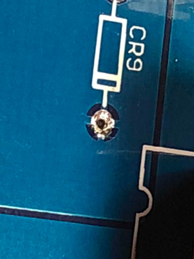
Thanks Mike. Had to remove the diode. Thanks to Curtis for sending a new one. The top of one pad looks muddied up, but not necessarily lifted. Connections look good to the surrounding board? I think it should be fine when we re-solder a new diode. How does it look to you? (photo should be attached). The bottom looks fine. Is this a ground lug and are the top and bottom connected to ground so it would be ok even if this was damaged? Thanks very much.

Sean

CR9%20Upper%20Pad.jpg
 
seanweaverguitar said:
Thanks Mike. Had to remove the diode. Thanks to Curtis for sending a new one. The top of one pad looks muddied up, but not necessarily lifted. Connections look good to the surrounding board? I think it should be fine when we re-solder a new diode. How does it look to you? (photo should be attached). The bottom looks fine. Is this a ground lug and are the top and bottom connected to ground so it would be ok even if this was damaged? Thanks very much.

Sean

CR9%20Upper%20Pad.jpg

It only connects to the ground plane on the top side.  Looks like it should be ok.  After you install it, check the continuity of that lead to another ground pad. They all have the cross hairs look.  If it's damaged you'll have to wire the lead to the next closest ground pad with a wire jumper.

Mike

Mike
 
Many thanks Mike. It tests to other cross-hairs on the top side and I will check it when I put in the new diode. I'm a bit confused, because there are cross-hairs on the bottom of that hole also, so aren't the ground planes connected on both since there are cross-hairs on both sides of that hole? Much appreciation for a great product.
 

Latest posts

Back
Top