[BUILD] New FET/RACK Official Help Thread - Please read first post!

GroupDIY Audio Forum

Help Support GroupDIY Audio Forum:

This site may earn a commission from merchant affiliate links, including eBay, Amazon, and others.
seanweaverguitar said:
Many thanks Mike. It tests to other cross-hairs on the top side and I will check it when I put in the new diode. I'm a bit confused, because there are cross-hairs on the bottom of that hole also, so aren't the ground planes connected on both since there are cross-hairs on both sides of that hole? Much appreciation for a great product.

True, looks like the board has a dual plane (I didn't lay it out).
 
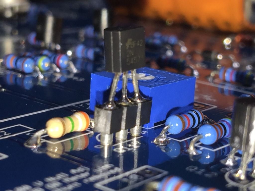
I owe you guys a handwritten thank-you note. The replacement CR9 diode showed up in the mail yesterday and the reinstall went well. Onto the Q1 & Q11 FET's with the sockets I ordered from your Mouser link, I got a little confused...In the Build Guide it says, "Note that the sockets are soldered to the PCB, the transistors are pushed into the sockets and soldered."

I wasn't sure how that would make removal/troubleshooting any easier with the transistors soldered into sockets instead of onto the PCB, but did solder them into the sockets before realizing that maybe I was misunderstanding the build guide to say they should be pushed into the sockets and then the sockets are soldered? I noticed in the pictures that there was no solder on the transistor/socket joints in the Build Guide pictures....after the whole thing was soldered!  If by some chance I did not misunderstand and did this exactly as intended by the manual, what would the advantage be of soldering to the sockets?

Thanks again Mike,

Sean

(p.s. in any event, I learned from the CR9 fiasco to not mess with anything unless it's broken but clarification would be helpful for the next order (as soon as I finish this one and get a few more funds together you'll get another Rev. A order from me; the idea is a pair for stereo linking. It'll happen....I want you to take my money again soon (as soon as I get one working first). Thanks again for being top class).

IMG_3922.jpg
 
(Hopefully posting this in the correct spot) I got to the final stage of calibrating my Rev A and everything is good besides it not compressing. I went thru the troubleshooting guide and narrowed it down to my GR Control Amp In and Out due to reading basically no voltage when testing against TP22 and CR2 (the GR Control Amp Threshold voltages looked good tho). I think all my solder joints look good and all the correct parts are in place, but I did put some transistors in the wrong place earlier in my build (prior to testing) and had to de-solder them to switch them. I feel like maybe I burned up one or more of the transistors. Does this seem logical based on what I've said (passes signal fine and all the other calibration was good)? I'd imagine it's best to re-install the Q7-Q10 transistors to start with? Since I can't remember which ones I switched them with, am I safer buying a complete set of all the transistors that look like those (Q12/13 are correct for sure)?
 
nolanthies said:
(Hopefully posting this in the correct spot) I got to the final stage of calibrating my Rev A and everything is good besides it not compressing. I went thru the troubleshooting guide and narrowed it down to my GR Control Amp In and Out due to reading basically no voltage when testing against TP22 and CR2 (the GR Control Amp Threshold voltages looked good tho). I think all my solder joints look good and all the correct parts are in place, but I did put some transistors in the wrong place earlier in my build (prior to testing) and had to de-solder them to switch them. I feel like maybe I burned up one or more of the transistors. Does this seem logical based on what I've said (passes signal fine and all the other calibration was good)? I'd imagine it's best to re-install the Q7-Q10 transistors to start with? Since I can't remember which ones I switched them with, am I safer buying a complete set of all the transistors that look like those (Q12/13 are correct for sure)?

You should be getting AC voltage to pad 22 with signal as described in the troubleshoot guide.  if you can't get AC V to there with GR ON, you have something wrong on your ratio PCB.

If you are, but seeing nothing on the output of the control amp it's possible you burned out a transistor desoldering it.  You can look at the schematic linked in the guide to test the voltages of the transistor legs to see which one is funky.

Q12/13 have to do with your meter.

Mike
 
Hairball Audio said:
You shouldn't solder into the sockets.  However I would just leave it unless you have an issue.

Mike

Thanks Mike. I gathered that after they were soldered!  I ordered a replacement matched pair from your site tonight just to be thorough, since I  figured it wouldn't hurt to have an extra set in any event
 
Hairball Audio said:
You should be getting AC voltage to pad 22 with signal as described in the troubleshoot guide.  if you can't get AC V to there with GR ON, you have something wrong on your ratio PCB.

If you are, but seeing nothing on the output of the control amp it's possible you burned out a transistor desoldering it.  You can look at the schematic linked in the guide to test the voltages of the transistor legs to see which one is funky.

Q12/13 have to do with your meter.

Mike


Seems to be something wrong with my ratio PCB then I think.  What's my best course of action to test here?
 
nolanthies said:
Seems to be something wrong with my ratio PCB then I think.  What's my best course of action to test here?

With GR ON and a 0dB signal on the input, you should have AC signal at PAD 15. Do you?

If so with GR ON do you have ACV @ either side of R78?

Mike
 
Hairball Audio said:
With GR ON and a 0dB signal on the input, you should have AC signal at PAD 15. Do you?

If so with GR ON do you have ACV @ either side of R78?


Yes, 4.009 ACV @ Pad 15.
No ACV on R78


Mike
Hairball Audio said:
You should be getting AC voltage to pad 22 with signal as described in the troubleshoot guide.  if you can't get AC V to there with GR ON, you have something wrong on your ratio PCB.

If you are, but seeing nothing on the output of the control amp it's possible you burned out a transistor desoldering it.  You can look at the schematic linked in the guide to test the voltages of the transistor legs to see which one is funky.

Q12/13 have to do with your meter.

Mike
 
The Rev A. is up and running, no smoke or fire but all is not well. I went through the calibration twice and can hear the compressor working but there are issues.

1. After calibration, when the Release knob is rotated back CCW, the meter drops. A lot. Like the meter goes back to -3  to -4 dB as my Release becomes more and more CCW. This is without any signal. I wasn't sure if that was an issue (I've never had an original and am always on the other side of the glass in sessions) but it didn't seem right to my limited mind and sent me through the troubleshooting guide to check all test points which is where it's become obvious it's not just my OCD or lack of understanding....(I'm using a Fluke 179 so the readings should be good)

2. With the Input knob all the way down, when I turn the knob up, the signal just comes "on" and then increases in volume naturally throughout the full rotation. But it's not a slow, even fade up from 0. It's off, on, then an increase through the knob rotation. Is this normal?

3. The power supply tests fine. 30 VDC on CR8 and -9.75VDC on CR9. 

4.  All test points are low in the Amplification Stages, but TP1 is only .1072 VAC (maybe that's still too far off but then it got worse). TP15 is an entire volt low and coming in at 2.86 VAC. TP17 comes in between .381 & .383.  The output transformer BRN and output XLR are way off though. Output BRN is 5.944 - 6.007. The XLR is only reading 5.858 VAC (which would've been pretty close if I'd tried a Rev. D!)

5. I put together Mark Burnley's signal tracer linked to from the mnat's website. But since I have a clear input and output signal is there any use in using it?

6. I didn't want to barrage you with listing every voltage in this note so I recorded them all in spreadsheet form for easy quick comparison if that helps at all https://drive.google.com/file/d/1LgX5w_UCuGMmMJVLTsXB6lBaI7ciC6-L/view?usp=sharing

I was dreading the troubleshooting because I was aware these are complex, everything took longer than intended, and my timeline to finish it up here is running out. I'm going home to Nashville on Monday but it probably makes a lot more sense to send it to you (and pay you of course) from Olympia than shipping it from TN...for shipping rates alone but to some extent I wanted to learn even more than to have a working compressor so that's what creates the conundrum.  Given endless time I'm sure I could see this through. With two days left...maybe not. I'm at a loss and a bit discouraged now so I guess I'll try some more tomorrow and see how in over my head I really am (lots, I suspect)...I guess I'll start with checking all solder joints again after I sleep the depression off. I spent hours with the eevblog videos and then practiced tons before the Lola build which went perfectly. Every component the Fluke could measure was measured, labeled in a bag, and then measured like 2,000 times again moments before installation, so it's something in my build (I read every word on your site & mnat's and really thought I could do this!!!)
 
With GR ON and a 0dB signal on the input, you should have AC signal at PAD 15. Do you?

If so with GR ON do you have ACV @ either side of R78?

Mike


Yes, 4.009 ACV @ Pad 15.
No ACV on R78

-Nolan
 
nolanthies said:
With GR ON and a 0dB signal on the input, you should have AC signal at PAD 15. Do you?

If so with GR ON do you have ACV @ either side of R78?

Mike


Yes, 4.009 ACV @ Pad 15.
No ACV on R78

-Nolan

Check your relay and ratio PCB connectors.  Make sure all the solder joints look good and reflow/test again.

Mike
 
seanweaverguitar said:
The Rev A. is up and running, no smoke or fire but all is not well. I went through the calibration twice and can hear the compressor working but there are issues.


1. After calibration, when the Release knob is rotated back CCW, the meter drops. A lot. Like the meter goes back to -3  to -4 dB as my Release becomes more and more CCW. This is without any signal. I wasn't sure if that was an issue (I've never had an original and am always on the other side of the glass in sessions) but it didn't seem right to my limited mind and sent me through the troubleshooting guide to check all test points which is where it's become obvious it's not just my OCD or lack of understanding....(I'm using a Fluke 179 so the readings should be good)

The release/attack setting should not hugely change your meter with no signal just sitting there.  Maybe fractions of a dB but not that much.  Not sure what that could be,  Maybe a bad pot or leaky FH333 diode. I know I've seen that issue before and fixed it, I just don't remember what it was. I'll have to think about that one.

2. With the Input knob all the way down, when I turn the knob up, the signal just comes "on" and then increases in volume naturally throughout the full rotation. But it's not a slow, even fade up from 0. It's off, on, then an increase through the knob rotation. Is this normal?

That's normal for those pots.  There is no perfect TPad out there. The UA ones are smoother from zero, but are prone to crackle in the first year. It's all a compromise. It should be noted that the input is not a volume pot, it's a variable 30dBish. So as you turn it down, just before it cuts out, is actually the end of the tpad.

3. The power supply tests fine. 30 VDC on CR8 and -9.75VDC on CR9. 

4.  All test points are low in the Amplification Stages, but TP1 is only .1072 VAC (maybe that's still too far off but then it got worse). TP15 is an entire volt low and coming in at 2.86 VAC. TP17 comes in between .381 & .383.  The output transformer BRN and output XLR are way off though. Output BRN is 5.944 - 6.007. The XLR is only reading 5.858 VAC (which would've been pretty close if I'd tried a Rev. D!)

Do you have your knobs on right? Line on the skirt lined up with "0"? 

5. I put together Mark Burnley's signal tracer linked to from the mnat's website. But since I have a clear input and output signal is there any use in using it?

Probably not.

6. I didn't want to barrage you with listing every voltage in this note so I recorded them all in spreadsheet form for easy quick comparison if that helps at all https://drive.google.com/file/d/1LgX5w_UCuGMmMJVLTsXB6lBaI7ciC6-L/view?usp=sharing

I was dreading the troubleshooting because I was aware these are complex, everything took longer than intended, and my timeline to finish it up here is running out. I'm going home to Nashville on Monday but it probably makes a lot more sense to send it to you (and pay you of course) from Olympia than shipping it from TN...for shipping rates alone but to some extent I wanted to learn even more than to have a working compressor so that's what creates the conundrum.  Given endless time I'm sure I could see this through. With two days left...maybe not. I'm at a loss and a bit discouraged now so I guess I'll try some more tomorrow and see how in over my head I really am (lots, I suspect)...I guess I'll start with checking all solder joints again after I sleep the depression off. I spent hours with the eevblog videos and then practiced tons before the Lola build which went perfectly. Every component the Fluke could measure was measured, labeled in a bag, and then measured like 2,000 times again moments before installation, so it's something in my build (I read every word on your site & mnat's and really thought I could do this!!!)

There is no shame in sending it in.  I've been repairing these builds for 10 years and they can still take me hours to figure out.  Sometimes it's just a perfect looking solder joint that isn't perfect underneath.

Check your transistor voltages in the signal and line amp sections.  There are links to those in the troubleshooting guide.  If your knobs are on right, it seems like you may have an under performing transistor. Maybe a 470Ω and 4.7K are swapped or something.

Mike
 
My kit did not come with 2n3707 transistors that were matched, to use for Q12 and Q13 also.
How did it work out for you?

Thanks Tony
 
Hairball Audio said:
The release/attack setting should not hugely change your meter with no signal just sitting there.  Maybe fractions of a dB but not that much.  Not sure what that could be,  Maybe a bad pot or leaky FH333 diode. I know I've seen that issue before and fixed it, I just don't remember what it was. I'll have to think about that one.
Thanks.  I spent the day reading every single one of the 973 (now 974) posts on this thread while taking meticulous notes on everything you and mnats said...while continuing to study the schematic which I don't really know how to read but am trying to learn. It gave me some more ideas for troubleshooting strategies but as usual am thinking about everything in the world that could ever go wrong now or in 20 years and way too out of touch with the moment. If I keep chasing this and if there is a faulty pot, I have deduced that the Bourns B25 is exceedingly hard to source. I couldn't find any in the store but would you have another for sale if need be? Otherwise, would something like the 5 Mohm Alpha pot (with that round base behind the shaft) have enough room to clear the Ratio board behind the front panel, like, if I had to wire one up from the pads? I don't want to waste your time with hypothetical questions but since now I'm wondering about the pot it made me wonder. Any perspective would be valued.
Hairball Audio said:
Do you have your knobs on right? Line on the skirt lined up with "0"? 
Yes. Exactly like that.
Hairball Audio said:
There is no shame in sending it in.  I've been repairing these builds for 10 years and they can still take me hours to figure out
Thanks for the kindness. I beat up on myself often and that makes me feel much better
Hairball Audio said:
Check your transistor voltages in the signal and line amp sections.  There are links to those in the troubleshooting guide.  If your knobs are on right, it seems like you may have an under performing transistor. Maybe a 470Ω and 4.7K are swapped or something.
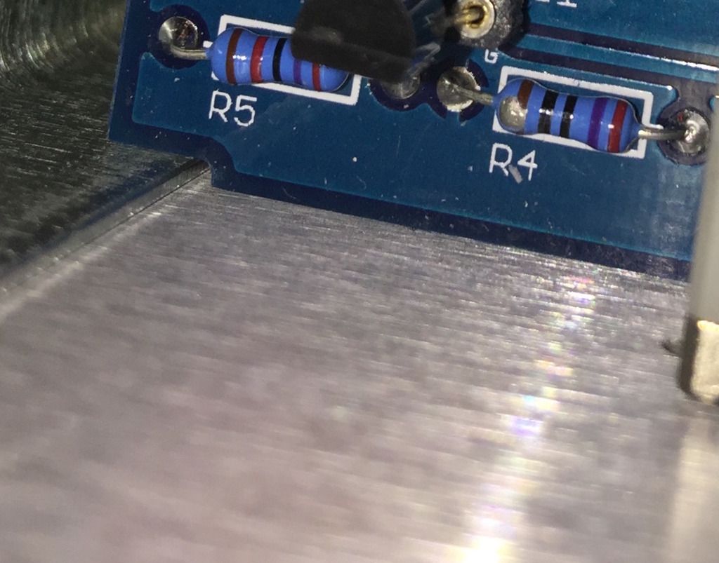
First thing I did notice visually is that R4 looks noticeably damaged. It's been chipped away somehow. Maybe from the Hekko getting too close to it while removing the hard-wired Q1 from the sockets and replacing the matched pair. In any event, it's reading way low. Like 12-ohms. I realize that's in circuit so I can see what it reads after taking one lead out but it seems to be a bit of a no-brainer & the first thing I'll try. I may just replace R5 along with it. I ran the transistor voltage tests & most of them looked  unsuspicious but....

At Q4, I got 1.91 VDC at the gate (you'd listed 2.21 VDC).  Then 4.72 VDC for Source (not 4.32). Then 12.22 VDC for Drain (13.38 was the number in your guide). On Q2 the Gate matched up but I was a little off on Source. I get 4.995 VDC (not 4.79). For the Drain I get 6.68 VDC (instead of 6.94). As I recall Q2 & Q4 are matched, correct? I looked in the store but could not find J309s. If it comes to replacing those let me know if you have a set available. I realize R4 is the obvious place to start and maybe it wouldn't hurt to replace R5 too. I should've left the soldered socket debacle alone like you said and probably screwed it up in the pursuit of perfection.

Right now I've put life on hold so much over the holidays that my visit up here's been extended to Wednesday to tie loose ends together like packing and laundry before I go but if there's a way to send out a couple resistors Monday let me know. They'd probably arrive by Tuesday. I'm almost crazy enough to drive north tomorrow (Sunday) to track one down if I can find one anywhere in Seattle/Bellevue/Tacoma. I don't presume anything is simple but am interested to see what happens.

IMG_3946_1.jpg
 
Sunday night update....it wasn't R4. I went north to Bellevue today and got a few more 1% tolerance 270-ohm 1/4 watts and it looked damaged but once the lead was out that resistor was still reading fine with the Fluke.

With the board out and back in the Panavise, I spent the rest of the night running continuity checks from the start to end of the entire main board. Maybe I wasted my time, I'm not sure, but at least it taught me more about the schematic.

I got continuity everywhere I should according to the schematic.

I noted just a few solder joints I didn't like the look of but is continuity continuity? Could a meter register continuity if the joint wasn't fine?

I don't really know what I'm doing but you saying maybe a leaky FH333 diode, I checked CR2 & CR3 with the ohms-meter and was getting resistance in the k-ohms range, which to my limited understanding...that wouldn't be leaky then right?

Tomorrow I'll go through and check the color codes again on the whole board

 
Okidoki, I completed my build, got the calibration sorted, and it was all going excellently, but after 2-3 days of use, I've run in to a couple things:

The input T-pad has become very scratchy/crackley - I've heard of this happening in older 1176 Tpads, but not so soon.. Is there anything that can be done to fix that or is it just a dud that needs to be replaced? I'll try reflowing solder/re-cleaning the PCB tonight..

When starting in GR mode, the meter starts high and takes a looooooong time to settle back down to 0. Like, about 3-4 hours.. I thought I read a post about it taking quite a while to settle, but now I can't seem to find it.. so, is that normal?
 
TonyW said:
My kit did not come with 2n3707 transistors that were matched, to use for Q12 and Q13 also.
How did it work out for you?

Thanks Tony

You'll probably fine, we don't send matched pairs with partial kits.  If they are not matched enough, you won't be able to set the NULL ADJ.

Mike
 
seanweaverguitar said:
Sunday night update....it wasn't R4. I went north to Bellevue today and got a few more 1% tolerance 270-ohm 1/4 watts and it looked damaged but once the lead was out that resistor was still reading fine with the Fluke.

With the board out and back in the Panavise, I spent the rest of the night running continuity checks from the start to end of the entire main board. Maybe I wasted my time, I'm not sure, but at least it taught me more about the schematic.

I got continuity everywhere I should according to the schematic.

I noted just a few solder joints I didn't like the look of but is continuity continuity? Could a meter register continuity if the joint wasn't fine?

I don't really know what I'm doing but you saying maybe a leaky FH333 diode, I checked CR2 & CR3 with the ohms-meter and was getting resistance in the k-ohms range, which to my limited understanding...that wouldn't be leaky then right?

Tomorrow I'll go through and check the color codes again on the whole board

You may have to pull them out to test them.  You should have a diode tester on your DMM.
 
shane said:
Okidoki, I completed my build, got the calibration sorted, and it was all going excellently, but after 2-3 days of use, I've run in to a couple things:

The input T-pad has become very scratchy/crackley - I've heard of this happening in older 1176 Tpads, but not so soon.. Is there anything that can be done to fix that or is it just a dud that needs to be replaced? I'll try reflowing solder/re-cleaning the PCB tonight..

When starting in GR mode, the meter starts high and takes a looooooong time to settle back down to 0. Like, about 3-4 hours.. I thought I read a post about it taking quite a while to settle, but now I can't seem to find it.. so, is that normal?

TPad sounds like a dud.  Email us.

If you mean it's a little off zero and takes hours to get to perfect zero, that is normal. That's why they put the adjust on the front panel.

Mike
 

Latest posts

Back
Top