


Echo North
Well-known member
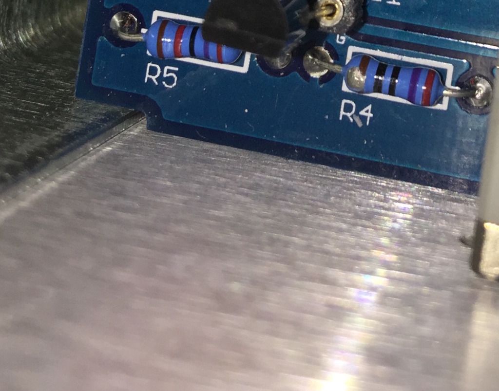
seanweaverguitar said:Thanks. I spent the day reading every single one of the 973 (now 974) posts on this thread while taking meticulous notes on everything you and mnats said...while continuing to study the schematic which I don't really know how to read but am trying to learn. It gave me some more ideas for troubleshooting strategies but as usual am thinking about everything in the world that could ever go wrong now or in 20 years and way too out of touch with the moment. If I keep chasing this and if there is a faulty pot, I have deduced that the Bourns B25 is exceedingly hard to source. I couldn't find any in the store but would you have another for sale if need be? Otherwise, would something like the 5 Mohm Alpha pot (with that round base behind the shaft) have enough room to clear the Ratio board behind the front panel, like, if I had to wire one up from the pads? I don't want to waste your time with hypothetical questions but since now I'm wondering about the pot it made me wonder. Any perspective would be valued. Yes. Exactly like that.Thanks for the kindness. I beat up on myself often and that makes me feel much betterFirst thing I did notice visually is that R4 looks noticeably damaged. It's been chipped away somehow. Maybe from the Hekko getting too close to it while removing the hard-wired Q1 from the sockets and replacing the matched pair. In any event, it's reading way low. Like 12-ohms. I realize that's in circuit so I can see what it reads after taking one lead out but it seems to be a bit of a no-brainer & the first thing I'll try. I may just replace R5 along with it. I ran the transistor voltage tests & most of them looked unsuspicious but....
At Q4, I got 1.91 VDC at the gate (you'd listed 2.21 VDC). Then 4.72 VDC for Source (not 4.32). Then 12.22 VDC for Drain (13.38 was the number in your guide). On Q2 the Gate matched up but I was a little off on Source. I get 4.995 VDC (not 4.79). For the Drain I get 6.68 VDC (instead of 6.94). As I recall Q2 & Q4 are matched, correct? I looked in the store but could not find J309s. If it comes to replacing those let me know if you have a set available. I realize R4 is the obvious place to start and maybe it wouldn't hurt to replace R5 too. I should've left the soldered socket debacle alone like you said and probably screwed it up in the pursuit of perfection.
Right now I've put life on hold so much over the holidays that my visit up here's been extended to Wednesday to tie loose ends together like packing and laundry before I go but if there's a way to send out a couple resistors Monday let me know. They'd probably arrive by Tuesday. I'm almost crazy enough to drive north tomorrow (Sunday) to track one down if I can find one anywhere in Seattle/Bellevue/Tacoma. I don't presume anything is simple but am interested to see what happens.
We can send you a new pot.


