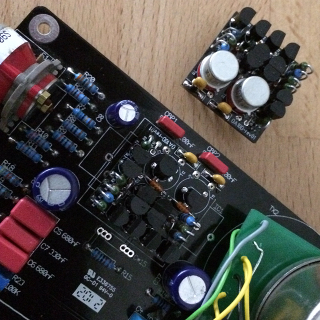
[BUILD] OV560 (Neumann OV60 in API500 format)

GroupDIY Audio Forum

Help Support GroupDIY Audio Forum:

This site may earn a commission from merchant affiliate links, including eBay, Amazon, and others.
Potato Cakes said:
Volker,

I have a pair of your kits completed and I'm trying to calibrate them, but it seems that the trimmer resistor isn't affecting anything. Is it possible that I have bad resistors? They pass audio and sound pretty awesome on bass, but I'd like to make sure they are properly set up.

Thanks!

the trimmer had originally the function to set to zero the offset on IC3  and than on IC4. The offset is given mainly by IC2's input bias current and after by the offset voltages  of the  following opamps.
Originally were used inside 741 IC's so the oofset was a problem. 
A  setting is needed for best headroom but a missing setting has not affect for the sound eccept for headroom and  "scrach" noise on R29, so for this reason you don't hear any difference.
Teorically you should set R22 for 0V offset on IC3 out.
I know the circuit because I make the MO6 replica.

Pier Paolo


BTW the circuit could be modified to eliminate R23 and leaving the same the original sound of this nice preamp, since it uses 5534's insted of the 741's , just adding a cap and doing a mod . 
 
So I made the adjustments and on both I now get -17dbFS going in and out with the gain all the way down and the trim to -12, which should be about right. I also changed out one of them with the Sparkos Discrete IC's, to see if that makes any noticeable difference with this design.

Thanks again for your help!
 
[silent:arts] said:
Janzoulou did a small listening test, comparing the OV560 to his origininal OV60:
Fonojet-Lunchtest.zip

Were those recorded as two different takes? Because the guitars sound different.  The OV560 really shines on the snare drum, sounds fuller, I much prefer it by far on that.


Silent:arts does your preamp sound similar to the Telefunken v376/v672 style of pres?
 
Testing my versions of the Neumann OA10 DOA.
Green Dot version works like a charm  :)

IMG_2157.JPG
 
Hello everybody,

I recently bought my OV560 kit from Volker, and it was real fun to build. However, there seems to be some short or some other fault in my build. When I switch on my Fredenstein Bento 6s with the module added, the voltage indication LEDs keep flashing. I’ve checked all solder joints, I’ve tried different slots, I’ve removed the HiZ plug-in, but whatever I try, the error is still there.

I talked to Volker and he suggested to ask the forum community. So where do I start my troubleshooting? Can I measure parts of the circuit, and what are the values I should expect? What components should I take a closer look at? Any other ideas?

I can add pictures later, if this helps.

Thanks a lot,
Claudio
 
So you buy the last ones !  :mad:
I wanted to buy another one but they was out of stock.
You will love them, when they work,

First of all, which led flashes ? The 48v and hi-z or just one of them.
How does it sound ?
 
Sorry for getting the last one. I couldn’t resist...

I should have made that clearer. It’s not the LEDs on the module, it’s the voltage LEDs on the front of the Fredenstein Bento 6s. Normally they just turn on and indicate that everything is okay.

See here: http://www.fredenstein.com/wp-content/uploads/2016/12/Bento-6S.jpg

And I haven’t had the chance to hear the sound yet. I obviously switched off the rack immediately when the error occured. But the flashing lights are reproduceable.

Thanks,
Claudio
 
Hello again,

Since there obviously seems to be something wrong with the voltage supply in my circuit, I checked the +16 and -16V pins against ground (without the HiZ plug-in inserted). +16V starts with about 750 kOhms and keeps rising (I stopped measuring when the DMM reached 1.2 Mega Ohms). -16V against ground gave me 4.46 MOhms and also kept rising. Is this normal behaviour? Could anyone with an OV560 please verify these values?

Thanks,
Claudio
 
Okay,
Thanks for the info.
I also use the Fredenstein Bento 6s with the OV560 without any problems.
So when you can use your lunchbox without the OV560 it’s definitely the Preamp.
I can check the values, when I’ve the time.
I think that you solder a resistor wrong, and the Fredenstein turns of, cause there a to many mA on the rail.
The value on -16 and +16 should be stable.
Maybe Volker can now help you, cause he’s the master.
 
I ask myself why the Bento LEDs are blinking. Can't google anything about this feature?
Too much current draw would burn either R35 and / or R36.
Measuring a rising resistance in circuit is fine since you are charging caps with your multimeter.
 
FYI, I contacted Fredenstein about the flickering lights, and this is what they replied:

Hi,
it looks like the module has a short, try it on a lab power supply before inserting it.
I don’t have a lab power supply, though. What now?

Claudio
 
Is undocumented switching of the PSU a feature or a bug? Must be that German engineering they advertise  :eek:
Cool. Not so much you can do without another Rack or PSU.
Post some high res pics so we can visually look for shorts.
Check if Q1 is the BC337 and Q2 the BC327.
Check if the NE5534 are inserted in the right direction.
The OA06 is tested and can't be inserted the wrong way so should be fine.
 
Volker, you are the man! I had indeed swapped Q1 and Q2. Seems like my eyes are already too weak for this tiny fineprint on transistors...

Anyway, I desoldered them, fixed everything (which, by the way, took me more than two whole hours!), and now the module is up and running. :) Can’t say how happy I am. Now I have to do some listening sessions next.

Thanks a million,
Claudio
 
To be honest another builder did the same mistake in December (and burned R35 / R36) so it was fresh in my mind  8)
Great this is sorted out, now enjoy your OV560  :)
 
To be honest another builder did the same mistake in December (and burned R35 / R36) so it was fresh in my mind 8)
Great this is sorted out, now enjoy your OV560 :)
Flashing lights. I did the same mistake too. When I found post from Claudio (day saver) I switched q1 and q2. Now I got a different issue as soon as I turn on power something on output pcb start to burn. I’m not sure what exactly because I don’t want to turn it on again but maybe it’s R35/36 too. Should I replace it?
 
I checked where is R35/36 located. Yes, it’s in area where I saw smoke. It would be easy to replace it. Did that guy in December burn resistors after switching q1/2 or before? Can it be something different? By the way I got 560 for api version.
 
R35 / R36 burn if there is too much current drawn.
Are you sure Q1 and Q2 are in the right place? (Q1 = BC337 / Q2 = BC327).
If they were in the wrong place before, they probably didn't survive.
 
Back
Top