[BUILD] STA LEVEL PCB OFFICIAL BUILD & HELP THREAD

GroupDIY Audio Forum

Help Support GroupDIY Audio Forum:

This site may earn a commission from merchant affiliate links, including eBay, Amazon, and others.
OK, so there is a lot of noise/hum/buzz in the audio.

I think it has something to do with the F+ heater circuit.

When I adjust the bias adjust trimmer between EL90's I can see a change occurring in the level on my interface input meter. However there is a good 20db of noise still. Only slight change.

I don't understand the test jig ON/OFF switch. I was measuring 6.3V between there and ground.

Appreciate this is DIY, but can anyone help out? I've gone over everything it looks ok, with no visible shorts, the voltages seem to add up ok as well. Not sure where this noise would be coming from. 

Many thanks

Gareth

--

 
Forget the momentary switch for now and check your wiring:

1) The 6,3V rail has got F+ and F-. F- needs to be connected to star ground. Of course star ground must be connected to IEC ground! If you do as described, you shouldn’t have any noise or hum at all. 

2) The connection F- to star ground can be made switchable by a momentary switch, which interrupts the connection to ground momentarily, when the switch is pushed. The lack of ground reference causes audible hum, which functions as a kind of “test signal “. So push down the momentary switch and trim the balance pots so that hum level is at its lowest level. Release the push button and you’ll have a perfectly balanced and hum free compressor.
Cheers
Bernd

 
Thanks Bern.

I have the momentary switch out of the circuit. I have two wires going from the two 'ground' points on the middle of the board, going to star ground. Star ground is also connected to IEC ground. All other connections to ground look ok and wiring seems correct.

 
Ok, then test a few things:
1) Feed the compressor with a test signal. Turn the  input pot fully counterclockwise. Is there still a signal ? If there is, then the input pot wiring is wrong.
2) Set the input pot to 12 o’clock. The output pot should only attenuate the signal , not completely shut down the signal
3) does the hum increase when turning up the input pot?
4) Set input pot to maximum and feed the compressor with a strong signal. Does the meter start to move? Distortion? If so, your 6ba6 input tubes are bad/broken.
5) Take out the 6AL5 tube and switch the unit on. Still hum? If not, your problem is in the sidechain. If yes, your problem is in the amplifier, probably bad tube, wrong wiring of the input or output  transformer.
6) have a look at  the wiring diagram in the first/second post once again. Check your wiring, especially the grounding !
This unit is the quietest tube unit I’ve got in my rack, so you made an error somewhere.
Cheers
Bernd
 
Thank you that’s good advice.

There’s definitely a fault somewhere, it’s not normal behaviour, will go through your suggestions.

Best

Gareth
 
1) Feed the compressor with a test signal. Turn the  input pot fully counterclockwise. Is there still a signal ? If there is, then the input pot wiring is wrong.

Input pot works fine.

2) Set the input pot to 12 o’clock. The output pot should only attenuate the signal , not completely shut down the signal

Works as expected

3) does the hum increase when turning up the input pot?

Doesn't really increase, does by turning the output pot. When I touch the casing of the input pot, hum increases a lot.


4) Set input pot to maximum and feed the compressor with a strong signal. Does the meter start to move? Distortion? If so, your 6ba6 input tubes are bad/broken.

Meter doesn't move at all, hard to say if it's distorting, I don't think so, might have blown something? As I turned up output pot there was a pop, maybe overloaded it too much?

5) Take out the 6AL5 tube and switch the unit on. Still hum? If not, your problem is in the sidechain. If yes, your problem is in the amplifier, probably bad tube, wrong wiring of the input or output  transformer.

Hum still there, there is now a lot more noise than before.

6) have a look at  the wiring diagram in the first/second post once again. Check your wiring, especially the grounding !
This unit is the quietest tube unit I’ve got in my rack, so you made an error somewhere.

Going to check wiring again, but it looks fine.

When I tap the 6BA6 tubes, whilst connected to audio interface, I can hear the tapping amplified, it's very loud, if I scratch the PCB I also hear that amplified. Is this normal behaviour? What does that indicate?

Thank you for any advice.

Gareth
 
Typical signs of wrong grounding/wiring.
A few things to check:
1) XLR in to audio in (pcb connector)  polarity, same with XLR out to audio out (pcb connector)
2) Check input transformer wiring
3) main board grounding (outer right connector to star ground)
4) the two frontpanel pcb need to be connected with wire bridges
5) check orientation of the „to/from ctrl“ connector

Cheers
Bernd

 
Hello, my STA is working fine but input signal is very strong and I can barely move the input knob
I can't compress normaly because lot's of color (distortion)


R 32 is 18K

also my B+ is higher spec I need to increase value of R3
R is 335v
A is 72,5
O is 333v

I have kidsquid power transformer and output Tpad
sowter in/out
alps dual 100K input potentiometer and 6386 tube

do I need to put a pad before input?

 
Decrease the signal before it hits the compressor and test if everything works fine. Normally the sta level has got a very hot output level. With the sowter 1:8 ratio it’s most likely, that you need an input pad. For the moment I wouldn’t worry too much about the B+ voltages.
Bernd
 
Thank you Bernd
I used it at mixdown and compared to LA2A, I sent normal level in both units and LA2A work as expected but with the sta I can barely increase the input.
I am not using the relay board  and I connected the xlr input directly to input transformer, I strapped the input pad with 0ohm resistor to bypass it , maybe I need to put the input pad back?
 
I built an H pad input 6db reduction
It's better like this


I also changed R3 with 1K to reduce my B+
I measured my voltage and some are off

this is what I have

are they normal?

A= 57,5v
B= 2.5mv
C= 1.33v
D= 0,65v
E= 01.33v
F= 3mv
G= 58.5v
H=109v
I= 164v
J= 3m
K=2,5v
L=2,55v
M=3mv
N=160v
O= 299v
P= 5mV
Q= 6.5mV
R= 298v
S=206v
T= 17.8v
 
A G H and T are very low compared to the reference voltage

it is okay?

A= 82v
B= 0v
C= 0,6v
D= 0,5v
E= 0,6v
F= 0v
G= 82v
H=142v
I= 168v
J= 0
K=2,58v
L=2,61v
M=0v
N=162v
O= 305v
P= 10mV
Q= 10mV
R= 305v
S=201v
T= 25v

does the trim pot in the psu section can fix that?

thank you
 
As long as your compressor works flawlessly I wouldn’t care to much about voltages. The reference voltages are taken from my prototype, just to verify, if we are in the ballpark. You could do some measurements with RMAA.
Cheers
Bernd
 
I didn´t read the entire thread, so maybe this has been addressed before. In case not here´s a problem I found:
I´m using Steve´s transformer with 5V AC for V+ and 5V relays. Without regulator installed I get 6,5V DC at the regulator input pin. With regulator installed the voltage drops to 4V at it´s input and I get 3,3V at the output. Several others have mentioned this before, but nobody did care.
The reason for this is that if we want to get 5V out of the LM317 regulator it needs to see at least 3V more at it´s input. But we only have 6,5V instead of necessary 8V. So it shuts down.

Several solutions are possible:
1) Throw D16, D17, R7, R8, V+ Trim, LM317, C17 out of the circuit. Connect 2 or 3 diodes (e.g. 1N4007), depending on what really comes out of your tranny, in series for a voltage drop of roughly 1,2 - 1,8V and solder them reversed (w.r.t. the silkscreen) into the D16 designation. Now we have an unregulated supply, but neither relays nor light bulbs care... Advantage here is the V+ is galvanic isolated w.r.t. everything else.
Edit: the unregulated output voltage depends a lot on how big the smoothing caps are. I have installed a total of 3000uF and still found the output voltage to be below 4V loaded, with the diodes across D16. So I skipped the diodes completely and simply installed a jumper. Now I get 5V.
2) Leave everything in circuit, but don´t use the 5V AC transformer winding to feed the V+ regulator circuit. Instead use the 9V AC output which is used for the filament heater by connecting the V+ AC input parallel to the F+ AC input. We lose galvanic isolation w.r.t. F+ that way, but it should not be a problem. Just make sure that the groundwire of the relay board doesn´t create a groundloop.
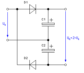
3) Skip the bridge rectifier circuit in the V+ section and cook your own voltage doubler circuit to feed the regulator input. It´s possible to install this into the PCB layout as it is.
Delonschaltung.GIF
 
Another issue I found:
C9 in the B+ PSU is rated at 400V. That´s too low. I measure 422V DC here. Theory says 300V AC x 1,4 = 420V DC after the bridge rectifier. So make sure that you use 450V rated caps for C9.
 

Latest posts

Back
Top