[BUILD] NU VARIMU 436 build & help thread

GroupDIY Audio Forum

Help Support GroupDIY Audio Forum:

This site may earn a commission from merchant affiliate links, including eBay, Amazon, and others.
Grooveteer said:
Bernd, Tony,

I'm playing with the FPD file provided earlier in this thread.  I see that the scales and the drill holes for the Lorlins are little offset.  (scales are slightly lower on the Y-axis than the drill holes)

Not a problem as I like to do my own scales, but I would just like to be sure that the drill holes are still correct.
Can any of you confirm this?

I can confirm that the holes are in the wrong place. I just downloaded the .fpd file myself to have a look, and immediately noticed this.
 
petermontg said:
I managed to get my noise floor close to -100. I had to ground my heaters for those wondering.

Best
Peter

Hi Peter,

That's a nice improvement.  How exactly did you ground the heaters if you don't mind me asking?

I'm getting close to finishing this one myself.  Might be a good idea to try once I get the stock version working.

Thanks.

Stefan
 
Grooveteer said:
Hi Peter,

That's a nice improvement.  How exactly did you ground the heaters if you don't mind me asking?

I'm getting close to finishing this one myself.  Might be a good idea to try once I get the stock version working.

Thanks.

Stefan

Hi Stefan,

I tied F- to common ground.

Best
Peter
 
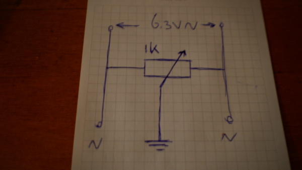
In old tube radio's you'll often find this small "Humm" pot on the back, it simply balances to a ground reference;

ov95BsR.jpg
 
Hello folks, I hope this message will find each of you in great shape ;-)

I need your lights please, my B channel won't pass audio when engaged...

Channel A seems working properly. Unit built with sowter xfmrs, 1,2mA meters (but I'm looking to get some nice 1mA). I made the tubes heaters wiring modification.

I already tried to swap one by one the tubes, the xfmrs, the cabling (internal and external), but nothing... I tested the relays and they work fine. Now I'm stuck !!

I tried to trace the signal with the same test tone on each bypassed/engaged channel with a DMM to compare them and found a strange behavior on B channel: The signal is getting very low at the input when I engage the B channel. Looks like a short somewhere in my circuit ?
When comparing I also found that for all tubes plates pins I had greatly lower voltages than the ones on A channel when the unit is engaged (like 230V vs. 150V).

If this symptoms tells you something, or if you can point me the right way to debug this channel, that would be wonderfull :) :) :)

Thx in advance.

Jerome
 
Hello folks, I hope this message will find each of you in great shape ;-)

I need your lights please, my B channel won't pass audio when engaged...

Channel A seems working properly. Unit built with sowter xfmrs, 1,2mA meters (but I'm looking to get some nice 1mA). I made the tubes heaters wiring modification.

I already tried to swap one by one the tubes, the xfmrs, the cabling (internal and external), but nothing... I tested the relays and they work fine. Now I'm stuck !!

I tried to trace the signal with the same test tone on each bypassed/engaged channel with a DMM to compare them and found a strange behavior on B channel: The signal is getting very low at the input when I engage the B channel. Looks like a short somewhere in my circuit ?
When comparing I also found that for all tubes plates pins I had greatly lower voltages than the ones on A channel when the unit is engaged (like 230V vs. 150V).

If this symptoms tells you something, or if you can point me the right way to debug this channel, that would be wonderfull :) :) :)

Thx in advance.

Jerome
Sorry for your troubles, maybe these have find a positive ending?
Maybe just a Resistor value error? Or just a bad solder joint?
If you say the relay is acting fine, then this takes out the "errata" i made for this one, but double check if there is continuity on the repair,
never know.

Unfortunatly i'm just selling the PCB, and haven't build the thing, my partner Bernd has, but he is off the business now, i just continue
selling these and if there is interest (reorders only if interested).
WM helps this Forum as well, so (y).

Bernd took care of for the support thread, but he decided to leave it for a while.
We go by the principle that most of the obvious errors have been covered up, so we leave this to the generous help of the members who have run into same kind of troubles or else....
Most Troublshooting are anyway going around the same procedures of triple check etc... and distance and not beeing the guy who builded it, doesn't make things easier for helping.

Hope you'll get to the bottom of the problem
 
Hello folks, I hope this message will find each of you in great shape ;-)

I need your lights please, my B channel won't pass audio when engaged...

Channel A seems working properly. Unit built with sowter xfmrs, 1,2mA meters (but I'm looking to get some nice 1mA). I made the tubes heaters wiring modification.

I already tried to swap one by one the tubes, the xfmrs, the cabling (internal and external), but nothing... I tested the relays and they work fine. Now I'm stuck !!

I tried to trace the signal with the same test tone on each bypassed/engaged channel with a DMM to compare them and found a strange behavior on B channel: The signal is getting very low at the input when I engage the B channel. Looks like a short somewhere in my circuit ?
When comparing I also found that for all tubes plates pins I had greatly lower voltages than the ones on A channel when the unit is engaged (like 230V vs. 150V).

If this symptoms tells you something, or if you can point me the right way to debug this channel, that would be wonderfull :) :) :)

Thx in advance.

Jerome
Hi Jerome

Whats your scenario around the Rtrim in the B+ line?
Your points that are marked on the PCB D,E,F etc etc?
Whats is your reading before the 10K resistor and across the CT

Best
peter
 
Hi Peter,

I replaced my meters with 1mA ones.

I left Rtrim empty and I get 330VDC on A point, 261 on B channel A, and 260 on B channel B.
Pretty high? I'm supposed to make the calculation to have Rtrim giving something like 245 on B+ ?

Other points readings, respectively on A and B channels, are as follow:
C 267,7 C 268,7
D 176,6 D 171,2
E 168,5 E 170
F 3,22 F 3,26
G 3,65 G 3,59
H 3,93 H 3,68
I 266,6 I 268
J 266,9 J 266,9

Looks like VR104 and VR103 tweaking have no impact on read values???

Thanks for your help ;-)

Regards,
Jerome
You should have a small difference with left right matching as it stands probably 1/1.5db max. I increased R1 to bring my values down if I remember correctly. I ended up with something around 1K5 there. Brings it down to 230V after the 10K/6k8 and across the CT. You could try there to bring it down. Your B+ needs to be closer to 290V before the 10k resistor

If the volume is lower on input I would be looking at the replacing the relay also

Your VR points should be balancing as close as possible L/R I think A difference of +/-1volt is best. If you can get the overall B+ down they might move. If not they could do with replacing
 
Last edited:
Hi all,

I´m slowly gathering all the parts I need to start building this nice unit.
What B+ Voltage should I aim for?
From the measurements from the protoype in this thread and most of your already built units, it´s somewhere close to 270VDC.
But if you read the comment in the bom about the trim resistor in the powersupply for b+, it looks like this would actually be designed for about 245VDC.
 
In BOM for PSU there are a few minor mistakes V+RLED 24V is 34.8K(4.8k), r6 24v is 3.6K. Mouser link are correct, but not everyone using them. May anyone explain hot to "tweak" rtrim to correct htrled on psu board?
 
Hi, I am also in for this build. Very exciting...
What is the better choise for the Output TX :
-Sowter 1232 (23k/150or600 Ohm) like Holger or Drip used .....or the
-Sowter 8650 (15k/185 Ohm) like mentioned in the BOM...
?
🤔 What is the better choise? Price is nearly the same.... I ve already ordered a pair of 1232 today because Holger also used them and they are advertised as Altec 436 replacements on the Sowter site....but I think there is more than enough time to change the order from Sowter😂 I think at least three months....🥴😓

As for InputTX I will try as big Lundahl fan the LL1540.
For the Meters I found on Ebay nice originally looking smaller 1mA Honeywell MM1's. They should fit better for this build on a 3HE 19" frontpanel than the bigger original MM2's on the Altec 436. And I love the powder green coated frontpanels from Altec ...🌶️🌋
 

Latest posts

Back
Top