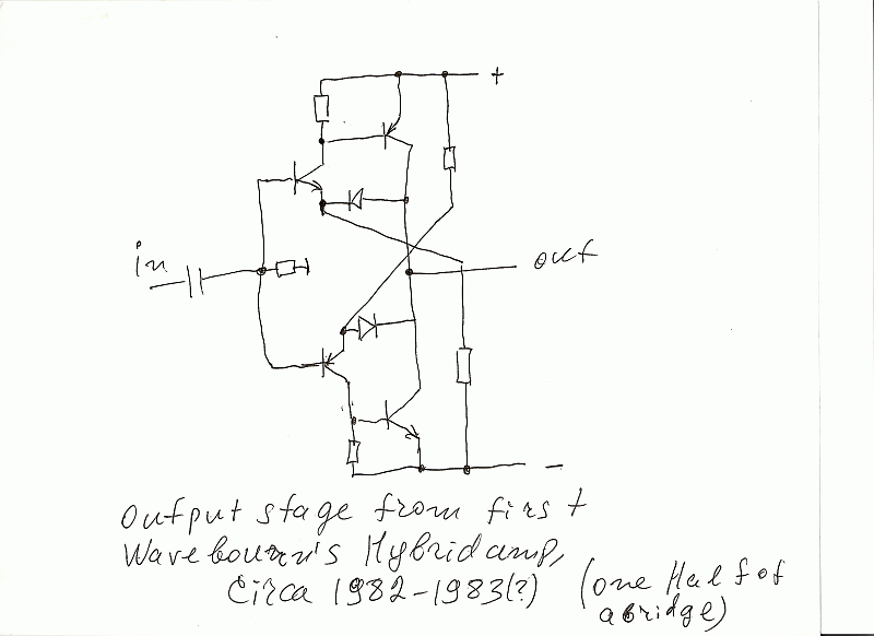
[quote author="clintrubber"][quote author="Wavebourn"]
Actually it is made of 2 complementary opamps loaded on each other, connected as voltage followers. Diodes instead of transistors are used because b-e breakdown voltage is usually very low (I saw only one transistor that had nearly equal b-c and b-e breakdown voltages, but it was a small signal one).
Can you improve it (except current mirrors instead of resistors between b-e of output transistors)?[/quote]
Interesting & funny, was first taking it for two CFP-stages, but then understood those diodes are in fact 'doing' the right BJT of a LTP.
[/quote]
Right. If I had transistors with high B-E reverse breakdown voltages I would probably use them instead of diodes. Overload protection means high voltage on them when output is shorted. Interestingly, it sounds "tubey" as people said, probably because of very soft clipping! The drawback is, resistors in tails has to be selected and their values depend on beta of output transistors. Fortunately, I had then already selected transistors with beta = 100 and CE breakdown voltages = 200.
So I figure the thing would work also without the diodes but dunno how/if performance would drop.
No, without diodes you will need some bias adjustment on bases and some temperature compensation. Also, an output protection against high power dissipation will be lost. Without diodes you will convert operational amplifiers to voltage followers. You'll be not able to operate it in such an elegant class A like in my case; you'll need twice more of a quiescent current to operate in class A that means more heat per output power. Actually, my version is the way to kill many ducks by a single bullet. It is a
power amplifier, not a
voltage follower that tries to compensate non-linearities of a current amplification by 100% feedback.
W.r.t. using two of these mirrored on top of each other, is everything clean around the midpoint ?
On top? What do you mean? It is already symmetrical push-pull amp. I used 2 of them for a bridged output configuration (a speaker cabinet had something like 16 or 32 Ohm impedance, I don't remember). I took inputs from the same phase splitter that used to drive output tubes.
For push-pull I'd be more inclined to something like this below but admit right away that I haven't done any comparison w.r.t. performance of one of the other.
In case of tubes such a follower works great, but you should remember that a resistor on top converts current to voltage that feeds the bottom transistor that needs a current to operate more linearly despite of a resistor in it's emitter that improves things. A MOSFET would work better there.
One more drawback is, the bottom transistor provides phase - shifted current variations.
I have a better version of such approach when a voltage follower is loaded on a voltage to current converter. I can share it with you if you want.


