D-AOC PCBs - the building and help Thread

GroupDIY Audio Forum

Help Support GroupDIY Audio Forum:

This site may earn a commission from merchant affiliate links, including eBay, Amazon, and others.
It's not clear what value belongs to what position (at least not for me  :-[)

Please rewrite it.

The max position is when the wiper (pin 2) has contact (0 ohm) with pin 3.

Try measuring the resistance between ground and both sides of R103...
 
Thanks, I figured it out now. It was a defective pot, somehow this was only recognizeable when it was connected. That was the last time I used cheap pots. Now I'm thinking about putting all stepped attenuators in there...
 
I'd just like to say that this has become my favorite vocal comp!!
There's something about it thats just right, and it does something lovely to just about any singer. I love my 1176s and various others too, but this one is special. ;D

I haven't got any inside pics, but I can tell you i used jensens 10k:10k on the input and some edcor wsm 10k:600 on the output. I did most of the Kubi mods except the step up input transformer, and I still used the solen cap on the output. Tubes are mullards and phillips. I'm not too good with cameras tho, so excuse the average photo.
l_e6dfccf25dfa43e680852ca7ab6eade0.jpg


Btw its also quieter than most of my other comps too. I was expecting is to be noisier being valve, but I'm glad I was wrong.......

Thanks Analag, Volker, Kubi and everyone whos contributed to this thread....(sounds like a lame acceptance speech, i know..........)
 
Ok so i had a good look and couldn't find any details on this, how does the bypass pcb get connected to a switch... what sort of switch rather? is it when the two wires are connected together it is bypassed or how does it work.

I'd like to use a 2 pos rotary switch if at all possible.
 
TheGuitarist said:
I'd like to use a 2 pos rotary switch if at all possible.

it is possible.

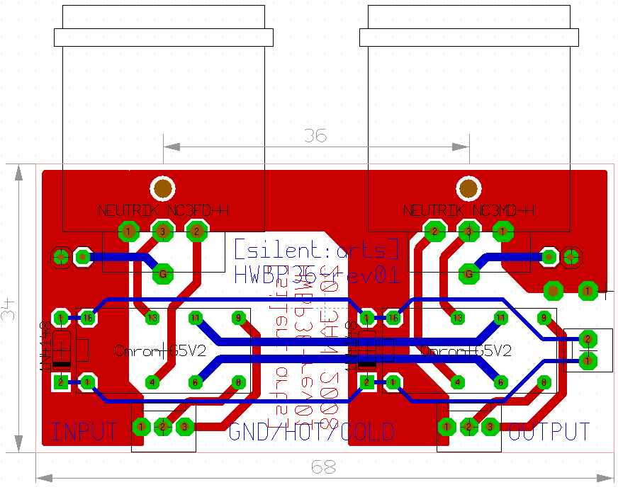
HWBP36.gif


with nothing connected it is in bypass mode.
pin 2 of the 2pin Molex on the right goes to the Bypass PSU GND.
apply the pos Bypass Voltage to pin 1 = no Bypass.
 
So basically all i have to do is just have the voltage going into the input of the switch, and then on the 2nd position (or 1st i guess) just have the tab that you'd ordinarily connect a resistor to, just connect the wire going back to complete the circuit.

Awesome.
 
Today i finally had the time to experiment with input transformers.

I allways had some hi freq loss with the edcor 10k/10k transformers and i had some LL1521's laying around (who doesn't). So i wired one channel with edcor and the other with the lundahl and man.. what a difference! Even on my cheapo (90 euro's) behringer monitors i have in the workshop i heard quite a big improvement in the hi-end.
So in installed the LL1521 on the other channel and went to the studio and man, it really sounds GREAT this way! Not only the hi-end improved a LOT but i also feel that the low end sounds tighter as well. Basically, the unit now upgraded from good to great!


No more edcors for me.. even tough they are cheap i don't like the sound. (pm670 low end loss counts as well)

Just wondering, i have 2 more 1521's, can i use these in the output or will i run into problems with impedance?
 
dagoose said:
Just wondering, i have 2 more 1521's, can i use these in the output or will i run into problems with impedance?
1521 won't work as output transformers as the ratio can't be better than 2,28:1 (if you parrallel the 1 + 1 )and you need minimum 4:1 ratio to be able to drive the 600 ohms loads.
In some cases, it'll work mainly with most new gear as their inputs are about 10K or more. But you'll find situations where your DAOC outputs will be loaded with a 600 ohm and the 12AU7 are not able to drive such a low impedance. You'll lose most of the signal  :-\ and you'll lose all the bass in the signal left  :'(... Don't go that way if you want to get a secure gear. Think about buying 2 good 4:1 output transformers... But I'm not sure you'll get a huge improvement. Edcors are not great transformers but they certainly give the gear a sound...
 
Just wondering, my D-AOC has some differences between left and right in the compression character which i think is coming from the vactrols. I swappad tubes and exchnaged the inputs trafo's with lundahls but i still have some differences going on.
Is there a way to match the vactrols? i received 4 new vactrols today so i can experiment but it would be better/easier to do some measuring before i start soldering. I'm also going to anti parallel the vactrols as in the kubi advanced version, i have 6 vactrols in total now so i think there must be a matched pair there.  ;D

Any idea how to match the vactrols?
 
dagoose said:
Any idea how to match the vactrols?

I asked this question and Kubi answered it, but I can't find it in this thread. I couldn't find the "advanced"  thread either.

You have to match the current between vactrols. Pick a voltage in the middle of the compression range and then find the current draw of the vactrol. I have an HP bench supply that has a current meter so it was easy for me to match them. If you don't have a current meter you can put a resistor in series with the output and measure the voltage drop. I think that last part is correct but I hope someone who knows will confirm.
 
While you are matching the LED's what about the photo-resistive element. I'm sure they don't drop resistance equally to the same level of illumination.
 
I did it before I had heard it. I figured it couldn't hurt. It sounds great so I know it didn't hurt.
 
OK, it looks like something was wrong with the vactrols i had in originally, like i said, i thought they had  quite a missmatch and both channels responded quite differently.
Today i replaced both vactrols just to try this out and suddenly both channels respond in the same way!  :eek:
After that I also paralleled the vactrol in reverse with another vactrol (order 4 new ones) and it does make a difference indeed! The other KUBI mods where in there before so now my d-aoc is a 100% kubi version. :) it now came alive and really sounds great! I can say that i love the d-aoc much more then my pooman now and i know i will be using it much more now.  8)
 
Just finished soldering. But my R1 is smoking like a chimney...  ???

An earlier post showed the same problem and it was solved by putting in 2x 1k 2W resistors in parallel, though they went hot, too. I put in the same amount, still it smokes the very second i plug it in.

I got 277VAC without load. Every piece in that region seems to be ok and in place. All diodes are in the right direction.

Can the problem be anywhere else?


edit: also the NE2 don't light up...

can someone help?
 
mischa said:
Just finished soldering. But my R1 is smoking like a chimney...  ???

An earlier post showed the same problem and it was solved by putting in 2x 1k 2W resistors in parallel, though they went hot, too. I put in the same amount, still it smokes the very second i plug it in.

I got 277VAC without load. Every piece in that region seems to be ok and in place. All diodes are in the right direction.

Can the problem be anywhere else?


edit: also the NE2 don't light up...

can someone help?

Micha, did you use the German mains transformer from the group buy ?
I'm in the UK and have approx 245v AC from the wall, German transformer is built for 220v AC so
I had almost 300v entering the board - a bit more than you but it was burning up a couple of parts.
Solution was to use a 1k 25watt metal body resistor between transformer secondary and the board.
That got my voltages down and no parts were stressed, cost just a few £'s

MM.
 
thanks for the tip MM, i'll try that.

I did no group buy, but my transformer (musikding/Badel Elektronik) was mentioned already in this context.

just now i pulled the R1 and measured 251 where R1 sits.

It's sunday, so i'll have to start drilling holes instead of buying the resistor...          :p

 
Mischa ( sorry for the typo earlier ! ) Make sure that you bolt the metal resistor to the case
as it still gets a bit warm - I'm able to touch mine, gets as warm as a coffee mug, which is fine.
You could go for a 50watt instead, which will stay very cool :)
You obviously just need one resistor in series with one of the secondary large voltage connections.

Just checked, due to my higher voltage, I needed a 1k1 so you may be fine with a 750ohm or so.

MM.
 
Back
Top