D-EF47 Tribute To Oliver Archut U47 Build Thread.

GroupDIY Audio Forum

Help Support GroupDIY Audio Forum:

This site may earn a commission from merchant affiliate links, including eBay, Amazon, and others.
Check the physical condition of the connectors as well as the solder joints of all connectors. Check the solder joints and physical condition of the jacks on the PSU and the mic. I have a PSU on one of my own mics with a bad jack where if you wiggle the cable it makes noise and I need to change that XLR jack out, so you may want to check for that issue on yours. Check the tube mount. You may try a different capsule to see if the problem is capsule related. Check the capsule wires to see if connection is loose or capsule wire solder joints are loose. Check cleanliness of all hi-z areas, very important. Try a different tube. Make sure solder joints at trafo connections are solid. You can use the chopsticks method with the mic or psu open to touch different things with the non-conductive wooden stick and listen to see if you can identify the issue or a bad component that way. Does it happen before components warmup or is heat not a related issue? You can get that cold spray stuff to help you with trouble shooting that if you think it is heat related. Of course it goes without saying if you are testing anything that is open while the mic/psu is powered on use extreme caution and one hand behind your body if possible to avoid shocking yourself dangerously.
 
When you manipulate the cable grounds, use your DVM to check continuity between the mic body and earth ground (power supply chassis). It's easy to try so many things when troubleshooting, that you make a grounding mistake.

What body are you using? Is it XLR at the mic? it could be that the connector itself is loose. Wait, re-reading your post, does the problem only follow the cable?

Did you put heat shrink over each wire inside the cable? I slide heat shrink up each wire, slip a heat sink on while soldering, then slide the heat shrink down. Inspect both connectors. Are all the pins sticking out the same distance on the male end? Does the female end have any pins pushed inside the connector?
 
Hi Both,

Thanks for your suggestions - v useful points, I’ll check this through in the workshop over the weekend.

The problem I have now found does not follow the cable - so as you say checking the grounding throughout is a good idea - the shield does connect to IEC ground but I will do more thorough investigations!

I very much appreciate your quick responses - apologies for the later reply, I’ve been in sessions flat out this week and having picked up the issue, suddenly ran out of time…

All the very best
Update to this - it was indeed grounding related - problem turned out to be solved by linking 0v and shield in the mic body base - (a very helpful microphone tech made this suggestion) connectors still rustle every so slight but no cable noise when moved. (More investigation with shielding the binder connectors to follow) Movement noise was rippling up and down the 0v rail so linking them allows it a path to ground.
I had not linked the 0v to the mic body using the pcb hole mounts as found that created a ground loop - linking at the base of the mic effectively avoids this though
Right. And ideally, you terminate your cable shield immediately as it enters the mic body. I usually put a lug between the PCB rail and the bottom bell where the rail screws in.
 
Right. And ideally, you terminate your cable shield immediately as it enters the mic body. I usually put a lug between the PCB rail and the bottom bell where the rail screws in.
Yes, in fact I had done that with the cable shield, just not linked PCB rail there.
Cheers
S
 
Hi everyone, can anyone confirm whether this build works with the SCT2000 mic body? If not I'll look to grab a body from Ali Express. Thanks a lot!

EDIT: found out it doesn't. Going with an Ali Express body!
 
Last edited:
Hi everyone, can anyone confirm whether this build works with the SCT2000 mic body? If not I'll look to grab a body from Ali Express. Thanks a lot!

EDIT: found out it doesn't. Going with an Ali Express body!
I just finished building two of Dan’s D-EF47’s using Chunger’s Studio 939 premium 47 long body clones …

The PCB and the transformer used every available bit of space from capsule platform to mic base …

But it is absolutely worth it !

These mics sound amazing !
 

Attachments

  • IMG_9997.jpeg
    IMG_9997.jpeg
    1.9 MB · Views: 3
Hi everyone, can anyone confirm whether this build works with the SCT2000 mic body? If not I'll look to grab a body from Ali Express. Thanks a lot!

EDIT: found out it doesn't. Going with an Ali Express body!
Thanks for updating the thread. Makes it easy for someone to search SCT2000 within the thread.
 
No worries I actually ended up reaching out to Maggie from shuaiyin and she quoted me something around $85 USD for a 47 body which seems very reasonable and others have said their stuff is high quality. I'm aiming to order soon and will report back once I have them.
 
Buongiorno e buon anno a tutti, non essendo un tecnico chiedo gentilmente il vostro aiuto per portare a termine il progetto.
Non riesco a capire i 7 punti sull'alimentatore ei 7 punti sul microfono.
non riesco a trovare nussuno dove abito che mi possa aiutare.
Grazie Infinito
Roberto
 

Attachments

  • IMG_20231230_122145.jpg
    IMG_20231230_122145.jpg
    3 MB · Views: 2
  • IMG_20231230_122157.jpg
    IMG_20231230_122157.jpg
    2.6 MB · Views: 2
  • IMG_20231226_153907.jpg
    IMG_20231226_153907.jpg
    2.6 MB · Views: 1
Buongiorno e buon anno a tutti, non essendo un tecnico chiedo gentilmente il vostro aiuto per portare a termine il progetto.
Non riesco a capire i 7 punti sull'alimentatore ei 7 punti sul microfono.
non riesco a trovare nussuno dove abito che mi possa aiutare.
Grazie Infinito
Roberto
Buongiorno @Robby1970

Io, parlo italiano, è una lingua bellissima, mi piace molto.
Ma è meglio che tu scriva in inglese.
Riceverai più d'aiuta dalle persone qui, e pronto.

Speako the Inglese!
Or use Google Translate, è Buono. ;)
Buon anno 2024, amico mio.
Ciao Italia!!!🎉🍾🥂

PS.: Where In Italy (Or Svizzera?!?) do you live?

M
 
Good morning and happy new year everyone, not being a technician I kindly ask for your help to complete the project.
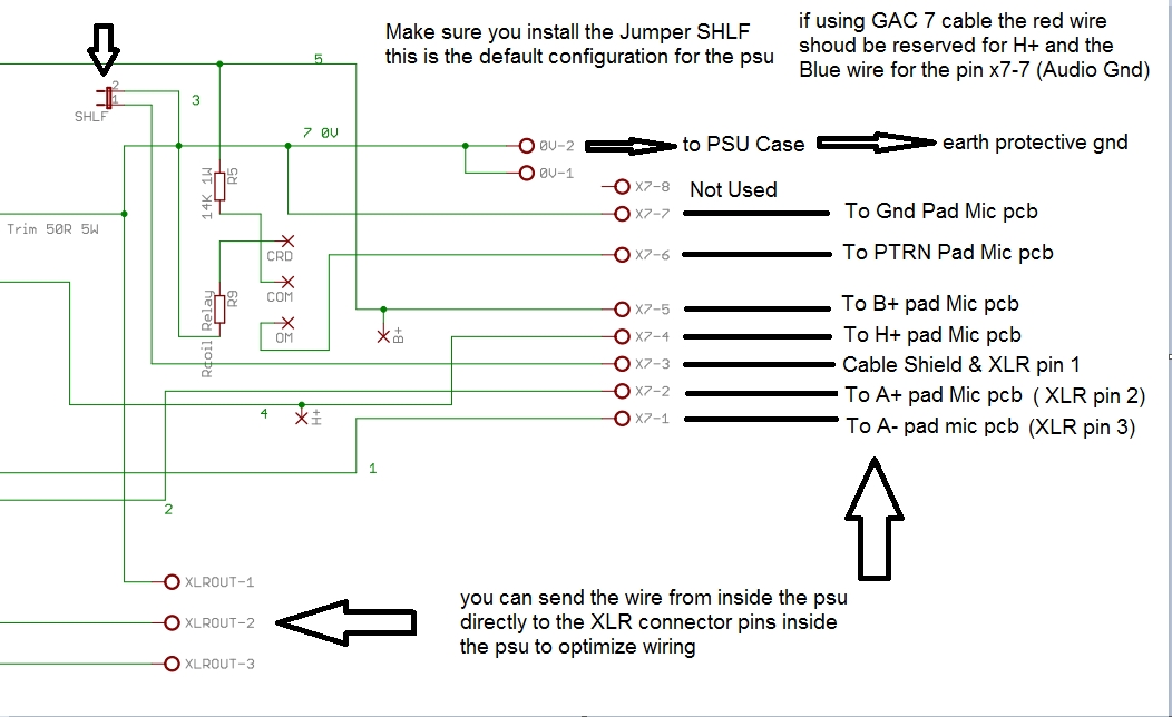
I can't figure out the 7 dots on the power supply and the 7 dots on the microphone.
I can't find anyone where I live who can help me.
Thanks Infinite
Roberto
 
Hope this will help,
Best,
Dan,

58d0281994573.jpg
@Robby1970
Maybe this will help you...?
It was posted by poctop on page 4 of this thread.
M
 
@Robby1970
Maybe this will help you...?
It was posted by poctop on page 4 of this thread.
M
I keep the resistor wiring in the power supply, and add two 1K resistors to feed to the XLR instead of wire, and bring the output z up to modern mic pre specs. I compare just sending out the signal vs. completing the H bridge with 1K resistors which resulted in a better noise floor at the preamp.
 
Thank you very much, Gentlemen, for this help

I ask for another courtesy
How should the output voltages be regulated?
 
The BV 8 transformer Ok?
Thank you
 

Attachments

  • IMG-20231225-WA0006.jpg
    IMG-20231225-WA0006.jpg
    28.1 KB · Views: 0
  • IMG-20231226-WA0007.jpg
    IMG-20231226-WA0007.jpg
    69.5 KB · Views: 1
Back
Top