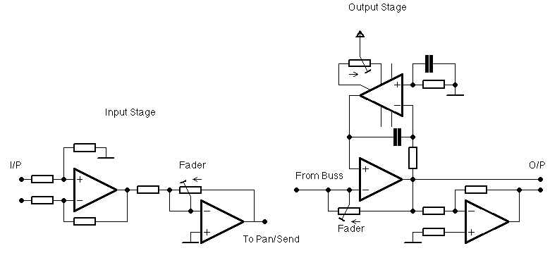
Send/Pan Schem
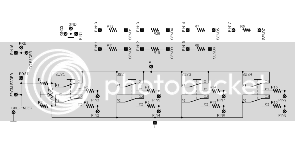
The pin# are I/O slot to a buss board. Send# is the retern from pin 2 of same send pot may be mono or stereo, using master pan or independent one)
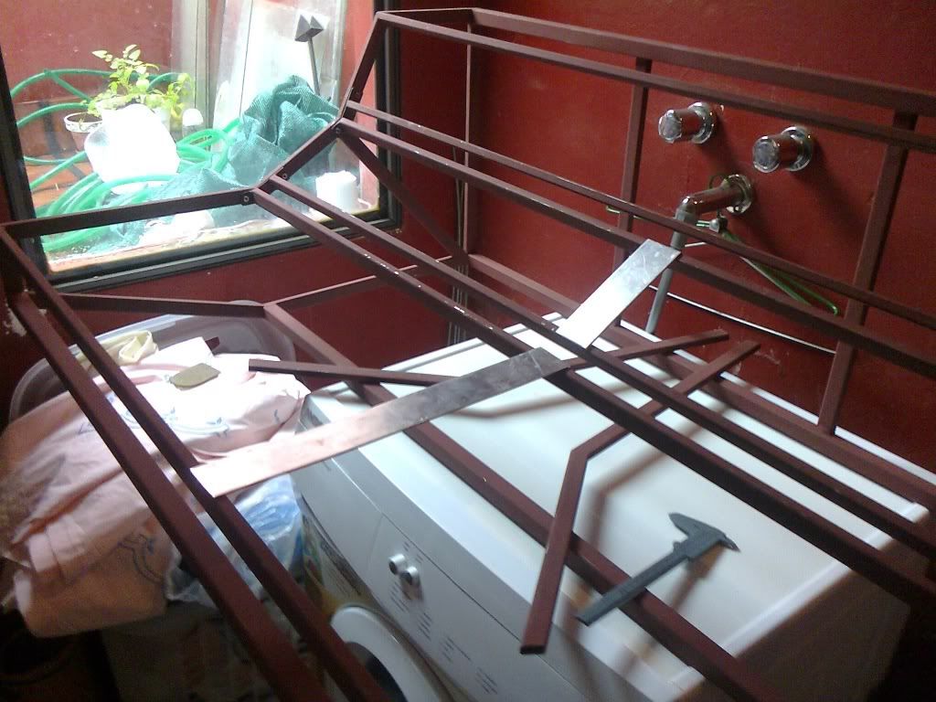
Here are some pictures I take today, just with the phone, sorry the quality. It's taking shape...
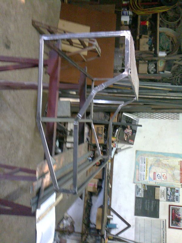
Side and little front pannels going to be wood, with conductive foil inside for faraday sheilding... thinking about the legs, maybe the same wood for the sides could be legs... what do you think? would be great any opinion here.
The pin# are I/O slot to a buss board. Send# is the retern from pin 2 of same send pot may be mono or stereo, using master pan or independent one)
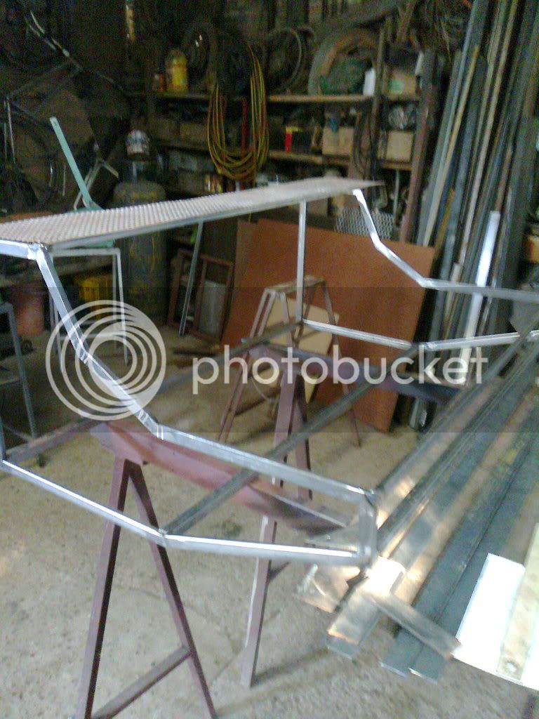
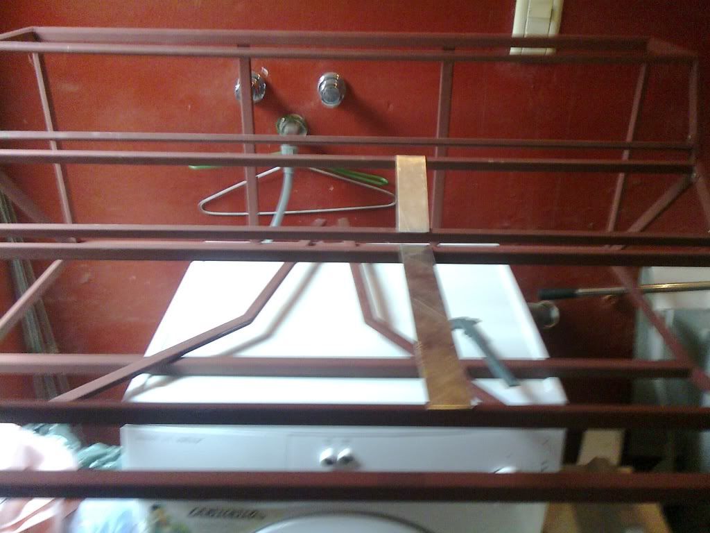
Here are some pictures I take today, just with the phone, sorry the quality. It's taking shape...
Side and little front pannels going to be wood, with conductive foil inside for faraday sheilding... thinking about the legs, maybe the same wood for the sides could be legs... what do you think? would be great any opinion here.
")