You are using an out of date browser. It may not display this or other websites correctly.
You should upgrade or use an alternative browser.
You should upgrade or use an alternative browser.
DIY JE-990 DOA
- Thread starter mnats
- Start date
Help Support GroupDIY Audio Forum:
This site may earn a commission from merchant affiliate
links, including eBay, Amazon, and others.
I don't have any plans to sell them, but my hope is that others will make boards from the Gerbers and distribute them locally. It doesn't seem sensible to ship a few 1.1"x1.1" boards halfway across the globe.
Etching them is only half the battle - without feedthroughs you have to solder certain components both top and bottom to complete the circuit. But I really wanted to include them in the PDF because some people might just want to try it out and won't have access to manufactured boards.
Etching them is only half the battle - without feedthroughs you have to solder certain components both top and bottom to complete the circuit. But I really wanted to include them in the PDF because some people might just want to try it out and won't have access to manufactured boards.
Very nice job!
Is the latest layout version tested&verified?
Jakob E.
Is the latest layout version tested&verified?
Jakob E.
Viitalahde
Well-known member
Thanks, looks cool! :thumb: I'm not sure I will ever build one though, I've understood it's a pretty tedious job. Will probably buy those from John Hardy..
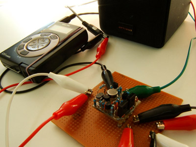
Yes, the layout has been tested as correct. I hadn't run any audio signals through it when I first posted, as my oscilloscope is still in transit from the US (sea freight). But this afternoon I decided to pass some audio :evil: Here it is driving an 8 ohm speaker to a pretty reasonable level:Is the latest layout version tested&verified?

It can apparently do this all day without heat sinks, just like Jensen says it can. Actually, he says it can drive a shorted output to full levels indefinitely. I'm not going to comment on the quality of the audio when I'm using a Rio mp3 player and a Radio Shack speaker, but I'll run some tests at school on Tuesday if I have the time...
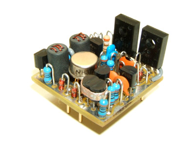
There are 41 components on a 1.1"x1.1" board, or 108 transistors depending on how you want to count :wink: It's a picnic compared to repairing boards full of BGAs at work, but still probably not everyone's idea of a good time. Still, a manufactured pcb with feed-throughs and a solder mask would make it easy compared to a home-etch. The Gerbers are there on my site for anyone to make and distribute boards...I'm not sure I will ever build one though, I've understood it's a pretty tedious job.
Al,
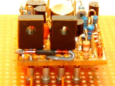
Yes. That was one of the things that some earlier layouts didn't seem to address too well. You can see the evolution of my layout starting in the middle of this thread. In the dale116dot7 layout, it looks like CR10 is touching Q9 but CR9 is coupled to CR3. I put pads at the edge of the board so the diodes can mount off-board and thermally couple to the output transistors.
The Fairchild transistors I used don't have the metal plate in the back that other brands seem to always have. But the collector leg seemed to give a good thermal link, and the diodes tuck right under the transistors that way:

This is great news. Thanks for doing this.
I think I remember someone on the forum discussing that the inductors are impossible to get hold of. Will just any generic 20 uH inductor work?
Will 1/4 watt resistors fit there?
Cheers,
Hejsan
I think I remember someone on the forum discussing that the inductors are impossible to get hold of. Will just any generic 20 uH inductor work?
Will 1/4 watt resistors fit there?
Cheers,
Hejsan
Someone has the correct inductors or there wouldn't be JE-990s for sale! But the answer to your first question is in the Jensen paper: "Alternative (inductor) constructions would require an analysis of the effects upon open-loop response, phase margin, and transient response." I'm hoping that others with more experience and skill will build it and do some tests themselves. The first thing that comes to mind for me is that the DCR will most likely be higher with off-the-shelf inductors.
I was Googling around last night and found an interesting thread with some surprising comments by some people known to The Lab regarding the emitter inductors.
You could drive a truck through the space required to fit the correct inductors. They are almost 6mm in diameter and a little over 10mm high. But I'm not sure why you would want to put a resistor there - the 30R resistors are already parallel to the inductors in the circuit.Will 1/4 watt resistors fit there?
I was Googling around last night and found an interesting thread with some surprising comments by some people known to The Lab regarding the emitter inductors.
chrissugar
Well-known member
Hey Mako
Great work. Thank you for doing it.
chrissugar
Great work. Thank you for doing it.
chrissugar
radiance
Well-known member
Indeed great work :thumb:
How long did it took you to build one? (not including the design), say the time from a pile of parts and a pcb to a finished product?
How long did it took you to build one? (not including the design), say the time from a pile of parts and a pcb to a finished product?
dissonantstring
Well-known member
hey mnats,
i've been following this thread and i just have to say GREAT JOB!:thumb:
you always seem to take on things most of us dread or simply overlook when there's something great to be had from building it correctly. i'm always amazed at the neat job you do, especially on something like a DOA.
BTW, i heard on the news that a cyclone went bowling through your way at 180mph wind speeds! :shock: hope all is well with you, your girl and your home. take care.
-grant
adrianh
Well-known member
mnats;
Finally someone posted a real Gerber file Yea!
This is how the big boys do it and now we here are doing it correctly.
These guys have a real nice Gerber viewer
that will allow you to print each layer. Just do not ask me how to use it.
You will need to give them your name and company name
so their marketing group know you are.
http://www.graphicode.com/pages/downloadprevue.cfm
Someone give Mnats a pat on the back!
The rf beads are sourced from http://www.fair-rite.com/
But the exact powder used they do not make anymore.
See the part# in the AES document.
Make a subsitution and get on with life.
[quote author="mnats"]
I just meant to ask if it was possible to use normal 1/4 watt resistors in this board (as resistors, not inductors :wink: ) I mean would they fit or do they have to be 1/8 watt types?
Cheers'n beers :guinness: ,
Hejsan
You could drive a truck through the space required to fit the correct inductors. They are almost 6mm in diameter and a little over 10mm high. But I'm not sure why you would want to put a resistor there - the 30R resistors are already parallel to the inductors in the circuit.[/quote]Will 1/4 watt resistors fit there?
I just meant to ask if it was possible to use normal 1/4 watt resistors in this board (as resistors, not inductors :wink: ) I mean would they fit or do they have to be 1/8 watt types?
Cheers'n beers :guinness: ,
Hejsan
jeez, do the boards have to be that small?
Hard to say exactly...I've made three so far...in between cups of tea, afternoon naps etc I would say about two or three hours. I spend a lot of time just looking at it trying to figure out which part to put in next so I don't paint myself into a corner, if you know what I mean.How long did it took you to build one? (not including the design), say the time from a pile of parts and a pcb to a finished product?
First of all, I don't think it would have happened without The Lab. There's a lot of knowledge in the back pages that I drew from and will continue to look probably for years to come. It's been about 10 years since Steve Hogan sent me a copy of the AES paper, I think. It would have still just been sitting there collecting dust if it hadn't been for the pool of knowledge here.Great work...GREAT JOB!...(etc.)
Secondly, I have a very selfish reason for building these things. So don't think I did it just for altruistic reasons.
Yeah, I didn't get to test out the amp at school tonight because I was experimenting with inductors. I'll post some questions and observations later...Make a subsitution and get on with life.
That's what's in the board pictured at the top of the thread - normal 1/4W 1% resistors.I just meant to ask if it was possible to use normal 1/4 watt resistors in this board (as resistors, not inductors) I mean would they fit or do they have to be 1/8 watt types?
Dunno, but it seems to be the standard so-called 2520 footprint. Hey CJ, I'm probably going to ask you some really dumb questions about inductors so hope you'll be around this thread...jeez, do the boards have to be that small?
Xopek - you might want to check this thread. But remember that pinouts on BCxxx devices are reversed to 2Nxxxx ones. Try out some replacements and let us know how they work.
What I was trying to say above is Thank You all who contribute to this forum - I couldn't have done it without you!
What I was trying to say above is Thank You all who contribute to this forum - I couldn't have done it without you!
clintrubber
Well-known member
[quote author="mnats"]because I was experimenting with inductors.[/quote]
FWIW, I saw the Jensen-patent had some specific coil-wiring arrangement through the bead. It's different from your pics but I don't think your experimenting is targeting this aspect of the inductors, right ? It'd surprise me if details like this are relevant, but who knows...
edit: ah, just read in the other thread you did need to do some experimenting here... was it in the end caused by the winding arrangement or the core material ?
Funny, I used a completely different winding pattern based on the photos of the TSS version here and the description in the AES text. Thank you, I hadn't thought of looking at the patent  So the TSS versions couldn't be using the pattern described in the patent text.
I'll try that pattern on the cores I have and measure them next week. But - and here's where my ignorance of inductors comes in - it seems to me that the total inductance is determined primarily by how many passes the wire makes through the core material. The text in the AES paper and patent seem to suggest that the reason for seperating the windings is to decrease the shunt capacitance of the inductor.
So I suspect that even though the core I found locally is the right size and shape, the material itself doesn't have the permeability of the core material suggested. It takes about eight passes through the core to equal 20uH with the bead I'm using. Of course this means that the wire passes through the same holes twice which I'm assuming will increase the capacitance and therefore will lower the resonant frequency...
How am I going to measure this with a generator that only goes to 1MHz or so?
Similar threads
- Replies
- 0
- Views
- 190
- Replies
- 6
- Views
- 217
Latest posts
-
-
-
Balancing card (2x unbal-to-bal & 2x bal-to-unbal) R vs G graph added
- Latest: MidnightArrakis
-
-


