EZ Tube Mixer Support Thread

GroupDIY Audio Forum

Help Support GroupDIY Audio Forum:

This site may earn a commission from merchant affiliate links, including eBay, Amazon, and others.
Hi Ian, hope your recovery is going well...

I've just seen you'd included in your docs an eq like the one I introduced couple of month ago  3bandeq/basiccct.png
I wonted to know if you have tried it and if you found any uses for it or is just there as reference? If it did I'm happy you make use of it, I've lost the track to all this project, universal eq included... If I had the money to build one I would be on board too, but at the moment is too expensive for me just to buy the tubes and transformers for a couple of channels but would be a good project for me when the time is right I think.

JS
 
I had  completely forgotten about that EQ idea. I remember we talked about it ages ago. I think that schematic was from LTSpice when I was playing about with it. The only issues I see is the law of the pots but this might make a good stepped control EQ, and whether the mid Q changes from boost to cut (like the Helios). Thanks for the permission to use the circuit. If I develop it further I will make sure you are credited.

Cheers

Ian
 
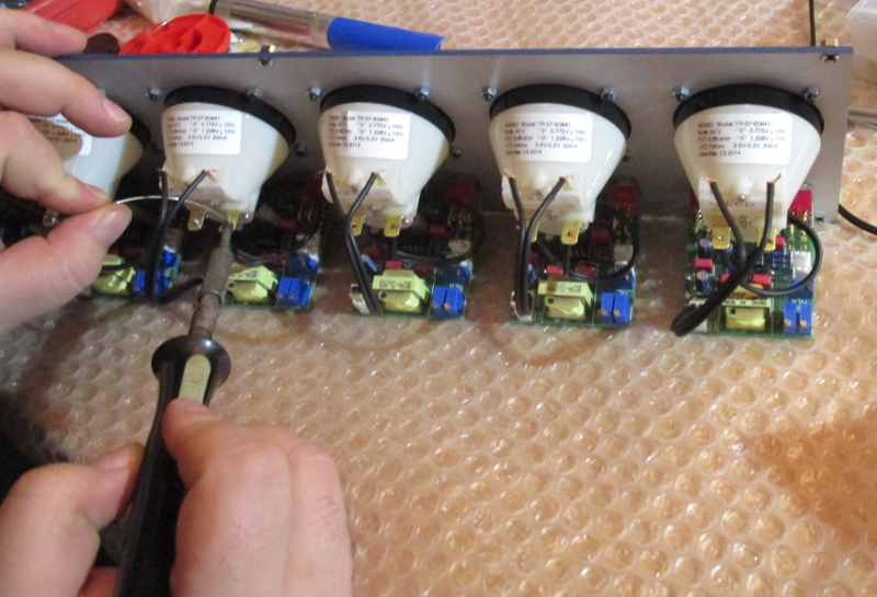
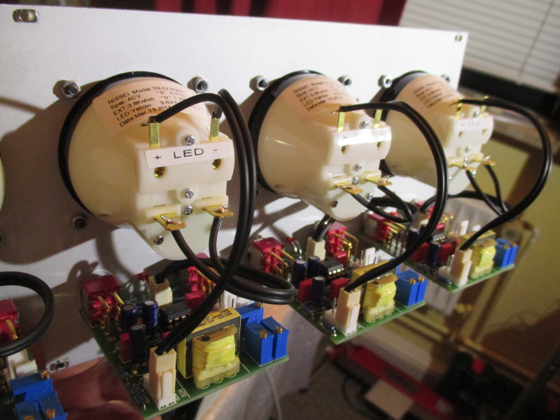
Today forum member Sven(dipfrik) helped me out and assembled the meter bridge, thanks Sven!

svenloetetmeter.JPG


meteralle.JPG


buffersdetail.JPG

 
Very nice job Holger.

BTW, it's not clear on the photo but are the 2 toggle switches the only support for the PCB? 
 
Thanks for that Ian, let me know if there any progress in this, if you develop something on it I'd like to know and try to build a couple just to have it around, I really didn't think it as a stepped controls since with a switch there are many others options which could make something like this better, free center tap in the first place which will make it dead zero at center, but if you find it useful go for it, I'd be glad.

JS
 
joaquins said:
Thanks for that Ian, let me know if there any progress in this, if you develop something on it I'd like to know and try to build a couple just to have it around, I really didn't think it as a stepped controls since with a switch there are many others options which could make something like this better, free center tap in the first place which will make it dead zero at center, but if you find it useful go for it, I'd be glad.

JS

From what I remember, the basic range of boost/cut is defined by R7 and R8 and the EQ pots need to have the same ratio at their centre position for a flat response. With regular pots this gives us two choices. If we use a LIN pot then R7 = R8 and the boost/cut is 6dB.  If we use a LOG pot, R7 = 9*R8 and we get 20dB of boost/cut. Personally I think 20dB is too much and 6dB is not enough which is why I was thinking of switched pots.

Cheers

Ian
 
The max boost is the relationship, the max cut would be limited by the Q of the cut filter, since it would end being an RLC filter, adding Q control will limit the max cut. Using a Log pot range could be limited, using a pot with a resistor to make the new law and the relation between R7 and R8 you want. The parallel resistor could be a trim pot to trim the center to zero.

Regards

JS
 
joaquins said:
The max boost is the relationship, the max cut would be limited by the Q of the cut filter, since it would end being an RLC filter, adding Q control will limit the max cut. Using a Log pot range could be limited, using a pot with a resistor to make the new law and the relation between R7 and R8 you want. The parallel resistor could be a trim pot to trim the center to zero.

Regards

JS

Yes you are right, the cut always has a potentially greater range than the boost which is limited by the pot divider. Whenever you have an RLC filter of this sort the Q ends up being greater for the cut than for the boost. The Helios is a classic example of this. The same is true of RC or RL sections in the sense that the shelving turnover point is different for cut than for boost. The Hlios overcomes this by using switched RC sections for boost and cut. The Q variation is overcome in the REDD EQ by using a different inductor for cut to maintain the same Q. The possibilities are of course endless.

I do like the idea of a slugged linear pot to obtain differing pot laws. My only concern is that they then represent a varying load to the source. For example, if you slug a linear pot with half its own value you get a centre point which is about 10dB down - quite a useful range for an EQ. The problem is the load the pot presents to the source now varies over a 3:1 range. Not a problem if you are driving from a low impedance source but it could be if you want to drive it from a 10K fader.

Cheers

Ian
 
ruffrecords said:
joaquins said:

Yes you are right, the cut always has a potentially greater range than the boost which is limited by the pot divider. Whenever you have an RLC filter of this sort the Q ends up being greater for the cut than for the boost. The Helios is a classic example of this. The same is true of RC or RL sections in the sense that the shelving turnover point is different for cut than for boost. The Hlios overcomes this by using switched RC sections for boost and cut. The Q variation is overcome in the REDD EQ by using a different inductor for cut to maintain the same Q. The possibilities are of course endless.

I do like the idea of a slugged linear pot to obtain differing pot laws. My only concern is that they then represent a varying load to the source. For example, if you slug a linear pot with half its own value you get a centre point which is about 10dB down - quite a useful range for an EQ. The problem is the load the pot presents to the source now varies over a 3:1 range. Not a problem if you are driving from a low impedance source but it could be if you want to drive it from a 10K fader.

Cheers

Ian

Yes, for a tube circuit may be a problem that, in solid state isn't since having two stages for an eq is cheap, not so much in a tube, maybe using before fader and accounting the fader as a load for the eq. Changing the inductor, or any filter properties between boost and cut using a stepped control is the obvious choice, my original idea was to get a really cheap passive eq capable of boost/cut with the same pot, as usual in more modern eq. I have a bunch of inductors and easy to get (600Ω telecommunication transformers in fact) which are roughly 250mH/1H which may be useful for this, and are ok for low-mid freqs, so maybe I'll end up building a couple like this, with a simple pot. Of course would make a better, more usable eq something better implemented, with stepped and changing Q from boost to cut to get a more symmetrical shape (not Q which is something like constant in fact in the case nothing is done, depending on the definition of Q in peak/dip eq, which isn't universal)

Regards

JS
 
I just finished the initial testing of the new V2 TwinLineAmp (TLA) PCB. This has a number of improvements over the original, many suggested by Holger. They include:

1. Molex connectors for all the interconnects within the PCB and to other PCBs e.g. EQ. So the internal mic and line connections are on Molex, as are the buses, the 48V/chassis, relay power and In1, In2 and Out1 and Out2 and the transformer secondaries.

2. The tubes have been moved a little towards the middle of the PCB. This means they will now easily slide into a standard 3U high extruded aluminium enclosure made by  Fischer without the possibility of the tube pins touching it (Holger uses these).

3. The gain trim pots have been moved to the front edge of the PCB so you can set the gain with a screw driver through a small hole in the front panel.

4. A 1N4007 has  been placed in series with the incoming HT line to prevent blowing caps if the HT is accidentally connected the wrong way round (I know, I did it).

5. A small HT decoupling cap has been added to solve the instability problem that can occur when several modules are connected to the HT supply.

6. The heater options for using the ECC99 have been removed.

7. The output cap of the first stage has been moved so it does not get heated by its tube.

8.  The electrical positions of the gain resistor and its  coupling capacitor have been swapped. This means one end of the gain resistor is now at 0V. This in not especially advantageous but it does mean that, if you omit the gain resistor, the free end of its coupling capacitor becomes a virtual earth point. So if you short the regular input and connect a bus to the free end of the gain cap you have virtual earth mixing. Each amplifier in the TLA then looks like an op amp with its + input grounded and a 47K from the output to the inverting input. Connect the bus to the - input and feed it via 47K resistors from channel modules to implement virtual earth mixing. I tried it this evening and I am pleased to say it works.


Cheers

Ian
 
Hi Ian,
  Is this for the old Eztube standard or the newer system i saw on your blog? Also i was wondering if you have a 2 module backplane left at the imporium, i would need another one eventually.

Regards,

Pierre
 
@Sven:

I only got 5 prototypes made in case there were any mistakes on it! One I have built and two I have sent to Holger to evaluate because he made such a great contribution to the alterations. So far it looks good but it needs thorough checking. When that is done I will order a batch and make them available via the emporium.

@Pierre:

This is 100% compatible with the original TLA. The connector is identical to the EZTubeMixer with the same pin out. It is basically the original PCB modified a bit. I have plenty of two module motherboards in stock.

Cheers

Ian
 
Hey Ian,

thats fine, i'll have look at the prototypes next time at Holger's "Custom-Tube-Monster-Chopper-Factory" ;)
Any update or progress on the next rev of the PSU board from the EZ Tube Lunch Box Project?

Thanks, Sven
 
dipfrik said:
Hey Ian,

thats fine, i'll have look at the prototypes next time at Holger's "Custom-Tube-Monster-Chopper-Factory" ;)
Any update or progress on the next rev of the PSU board from the EZ Tube Lunch Box Project?

Thanks, Sven

Only that it is on my list of things to do. The PCBs are in. I need to build one to make sure it is all OK, then they will be available from the emporium.

Cheers

Ian
 

Latest posts

Back
Top