EZ Tube Mixer Support Thread

GroupDIY Audio Forum

Help Support GroupDIY Audio Forum:

This site may earn a commission from merchant affiliate links, including eBay, Amazon, and others.
Holger said:
ruffrecords said:
...
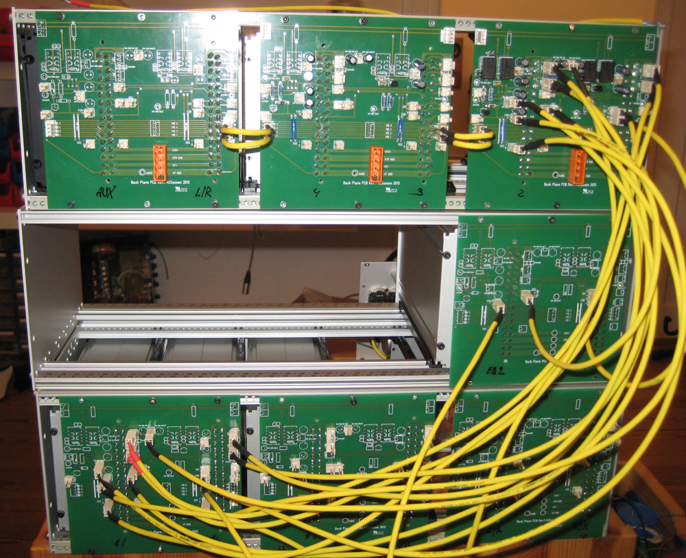
That is a good price for the PCBs. Did you stick to 1.6mm thickness?? I used 2.5mm for mine for some added strength.
...

1.6mm thickness. Another advantage of the relatively small PCB size.

I just checked the on line price of a PCB 128.4mm square with my two regular suppliers and both are more expensive the 9 Euros for 20 off. Where did you get the boards made?

Cheers

Ian
 
Holger said:
www.multipcb.eu

8.79€/piece ex VAT, shipping, handling
They also make custom toroidal power transformers.

Ah, I had not realised that was ex VAT & shipping, in which case my suppliers are much closer.

Interesting thing is that it turns out they are English, based in Poole in Dorset where I used to go on holiday as a kid. Now I shall definitely check them out.

Cheers

Ian
 
Hiya
About to start building a power supply, eventually to power a subrack of of EQ/compressor/preamps etc. I'll probably be mainly using the twin line amp card.
I gather that aswell as the HT supply, I also need a +/-12V supply for HTR ?

Are you using some off the shelf power supplies for this?
 
ramshackles said:
Hiya
About to start building a power supply, eventually to power a subrack of of EQ/compressor/preamps etc. I'll probably be mainly using the twin line amp card.
I gather that aswell as the HT supply, I also need a +/-12V supply for HTR ?

Are you using some off the shelf power supplies for this?

For my current  (sic) mixer build I am using an International Power linear off the shelf supply from Mouser:

http://uk.mouser.com/ProductDetail/International-Power/IHN12-51/?qs=0xCm9DOQnC7IFXnzVF5pSA%3d%3d

which will supply 12V at up to 5 amps; plenty for a single rack. Holger is building a bigger mixer and is using a 10 amp off the shelf regulator and a separate transformer. I am sure he will chip in an give the model number.

The International Power PSU is quite cheap but it costs about $40 for shipping from to the UK and then you'll have to pay VAT so it turns out not so cheap after all. I would suggest Holger's solution is better as it is quite happy at lower currents.

Cheers

Ian
 
More modular madness. I've started wiring today. This is time consuming.

backplanes.jpg
 
Your project is really beginning to come together Holger. You might like to think about bundling some cables together into bigger looms. You have spare tapped holes between the motherboards so you could possibly affix something there that could take a tie wrap.

PS. Are all those yellow cables done with crimp terminations?

Just a thought.

Cheers

Ian
 
Holger said:
I will clean the mess up once it is tested  ;)
All those cables are crimped. That's why I wrote that this is time consuming.

I wrote in my blog about my experiences with crimping. Do you have any tips?

Cheers

Ian
 
Hiya
While I'm waiting for some diodes and PSU bits for the compressor, I'm trying to understand a bit more about grounding. There seem to be a whole host of practices and competing ideas..
I've read the grounding 101 document which is great, but I have a couple of questions:

- On the twin line amp PCB, there is 1 single ground plane for all the audio ground connections I think - have I got that right? It connects to 3 pins on the DIN connector. Is there any reason for this?

- The chassis and input screens don't connect to anything on the PCB. The cable screens should then just be connected at one end. Should this be pin 1 of an XLR, and then all pin 1's are connected together and finally connected to safety/chassis ground? Or is there a better way?

 
Holger said:
More modular madness. I've started wiring today. This is time consuming.

backplanes.jpg

Thats exactly what i had in mind when we were discussing about modules and backplanes in the previous thread! Great work Holger! What is your target as far as number of channels for the whole console when finished?
 
ramshackles said:
Hiya
While I'm waiting for some diodes and PSU bits for the compressor, I'm trying to understand a bit more about grounding. There seem to be a whole host of practices and competing ideas..
I've read the grounding 101 document which is great, but I have a couple of questions:

- On the twin line amp PCB, there is 1 single ground plane for all the audio ground connections I think - have I got that right? It connects to 3 pins on the DIN connector. Is there any reason for this?

Yes, there is a single plane for the signal 0V (I think ground is a bit ambiguous as you will know from grounding 101). The reason it connects to three separate pins is to allow the management of the screens of unbalanced cabling internal to the mixer. One of the 0V is next to OUT1 and another is next to OUT2. If either OUT1 or 2 is used to drive a transformer then the return signal from the transformer should be connected to the nearby 0V. You should probably use a screened cable for this using the screen as the return. The other 0V is associated with the pins intended for fader connection and may or may not be used depending on the application. The attached schematic illustrates what I have said above.

- The chassis and input screens don't connect to anything on the PCB. The cable screens should then just be connected at one end. Should this be pin 1 of an XLR, and then all pin 1's are connected together and finally connected to safety/chassis ground? Or is there a better way?

The chassis pin is there to allow you to make a direct electrical connection to your module's metalwork if you wish. Usually you can rely on the mechanical fixing of the module into the rack to connect the module metalwork to the overall chassis.

The input screens do not connect to anything on the PCB because you need to use twin screened cable from those pins to the transformer inputs. On the PCB the screens should be connected at the 32way connector end and left unconnected at the input transformer end. The pairs of holes along the top of the PCB are intended for securing the screened cable. External to the module you should use twin screened cable with the screen connected both at the module end and to the XLR pin 1. Each XLR should have its pin 1 connected directly to the chassis at the XLR. There is no need to bus them together unless they are mic inputs being fed phantom power.

Cheers

Ian
 

Attachments

  • Mixer2wiresht2.jpeg
    Mixer2wiresht2.jpeg
    182.2 KB · Views: 0
Last edited:
To Ian and Holger,
    I was wondering when you guys designed the backplanes did you draw the foot print for the din connectors from scratch?  I have time to kill while waiting for my panels from Frank. I want to fiddle around with different ideas i have for a backplane. The only components i found yet are for the eurocard themselves...

Regards,

Pierre
 
anjing said:
To Ian and Holger,
    I was wondering when you guys designed the backplanes did you draw the foot print for the din connectors from scratch?  I have time to kill while waiting for my panels from Frank. I want to fiddle around with different ideas i have for a backplane. The only components i found yet are for the eurocard themselves...

Regards,

Pierre

I made mine from scratch. That's why the connector holes don't line up with the holes in the PCB - I made an error.  I used a manufacturers drawing to create it but I found the way it was dimensioned very confusing. I later had a discussion with Holger about this and he sent me a copy of a different manufacturer's data sheet. The dimensions on this were much easier to understand.

Cheers

Ian
 
Thanks Ian!
    That's what i tought! I'm going to look into it. I'm also thinking of making a smaller 19inch rackmountable frame or maybe a lunchbox so i can use the eztube modules outside of the studio.
      Is the crimping tool mentionned in your blog a generic one or is it the molex model? The part i find the most difficult is to have the crimps allign in mutiwire cables.

Regards,

Pierre
 
anjing said:
Thanks Ian!
    That's what i tought! I'm going to look into it. I'm also thinking of making a smaller 19inch rackmountable frame or maybe a lunchbox so i can use the eztube modules outside of the studio.
      Is the crimping tool mentioned in your blog a generic one or is it the molex model? The part i find the most difficult is to have the crimps align in mutiwire cables.

Regards,

Pierre

The crimping tool is a generic one:

http://www.rapidonline.com/Tools-Equipment/Crimping-tool-for-PCB-connectors-30535

It has one slot for AWG 24 - 30 and another for AWG 16 - 22. Getting the crimped wires the same length in a multi-wire cable is difficlt I agree. I think it is a matter of practice more than anything.

I was not going to mention it just yet but inspired by Holgers two module backplane PCB I have designed one of my own. The PCBs arrived this morning so I have not had chance to build one and check it out. It basically brings out all the signal connections to two and three way Molex headers into which you can plug their crimp connectors. I am sending one to Holger to play with. I'll send you one too.

Cheers

Ian

 
Elma has some pretty good resources on eurocard specs & dimensions if you are interested:
http://www.elma.com/services/us-resources/eurocard-specs/

I was wondering if you know whether it would be possible to mount a PCB at 90 degress to a eurocard, along the front plate in order to mount switches/pots etc and associated components (i.e for switched volume controls) ? Could it be fixed using the same brackets that fix the eurocard to the front plate?

 
ruffrecords said:
The crimping tool is a generic one:

http://www.rapidonline.com/Tools-Equipment/Crimping-tool-for-PCB-connectors-30535

It has one slot for AWG 24 - 30 and another for AWG 16 - 22. Getting the crimped wires the same length in a multi-wire cable is difficlt I agree. I think it is a matter of practice more than anything.

I was not going to mention it just yet but inspired by Holgers two module backplane PCB I have designed one of my own. The PCBs arrived this morning so I have not had chance to build one and check it out. It basically brings out all the signal connections to two and three way Molex headers into which you can plug their crimp connectors. I am sending one to Holger to play with. I'll send you one too.

Cheers

Ian

It's funny how we have the same things on our minds without communicating! I was thinking of placing a long due order for some pcbs, i'll email you.

For the crimper i have a similar one, i did a lot of research on the subject and it seems that the quality of crimper makes a big difference. The one from molex costs the price of several transformers! 

Regards,

Pierre
 
Back
Top