Fairchild 660 from scratch

GroupDIY Audio Forum

Help Support GroupDIY Audio Forum:

This site may earn a commission from merchant affiliate links, including eBay, Amazon, and others.

DaveP

Well-known member
Joined
Nov 8, 2005
Messages
3,183
Location
France
I've had a request for one of these from a studio, so here goes.

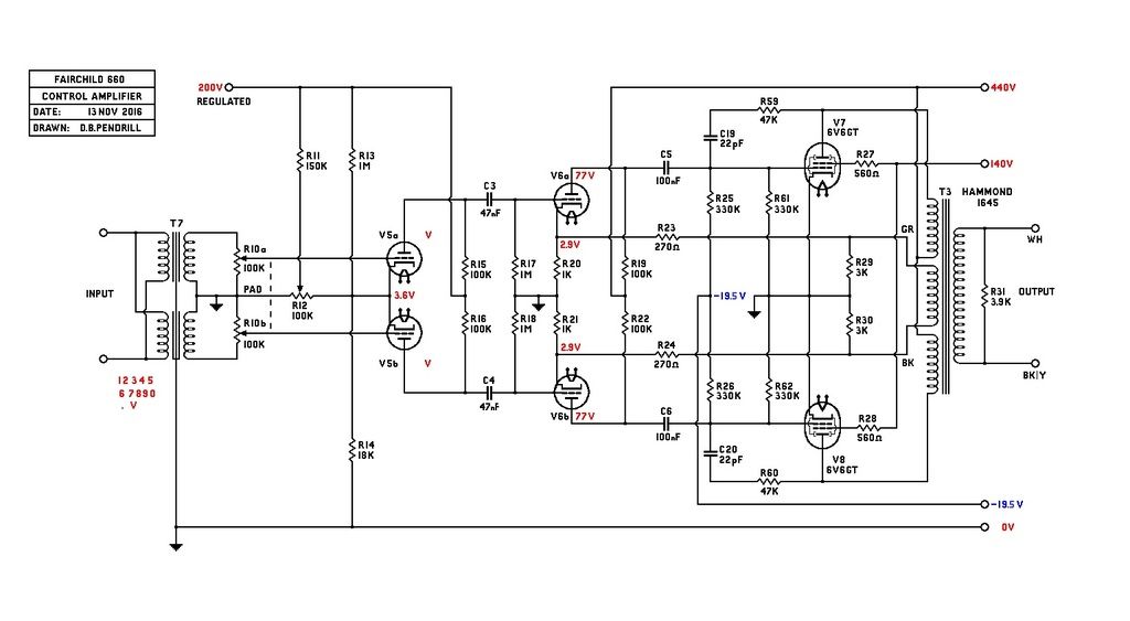
The transformers are available from Sowter but they will set you back a grand or thereabouts, but a Hammond 1645 before they changed the secondary wiring works very well for the control amp OPT.  The later 1645 obliges you to take the cover off to extract the 4 ohm wiring pair as one member here has recently done.  You can then use this pair as a tertiary for feedback, the rest of the 70V windings power the diode bridge for the negative CV, I've had it up to 100V DC on a test circuit.

The feedback resistors have to be modified from stock because the tertiary is obviously not the same, and the total values have to add up to the original or else the operating point of the 12BH7 is altered.  The stock values are 560 and 2700r but with the 1645 you need 3000 and 270 respectively, this gives you the required output impedance of 100 ohms which is essential to give you the attack of the 660.

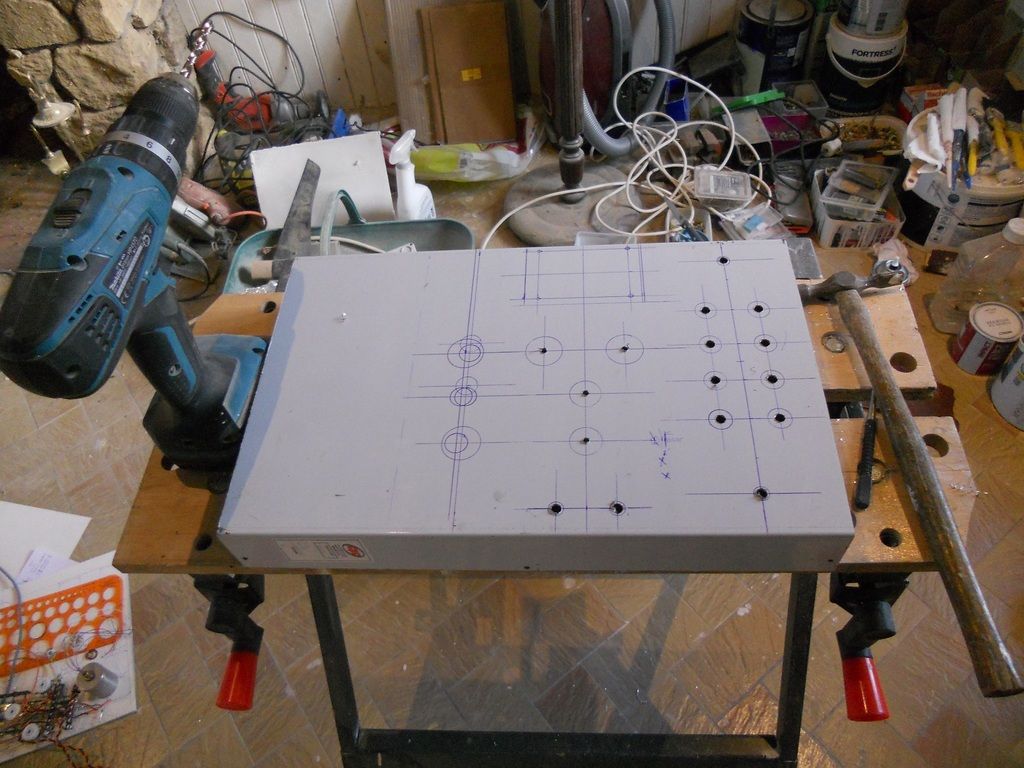
This is how they all start:-

This is my Control Amp schematic re-drawn from the original.  Very little changed from stock.

This build will continue over the next few months and was the reason I cancelled the EF85 project.

DaveP
 
bernbrue said:
I love your "from scratch" thread. Better than any lecture in audio electronics!

I'll second that!

These threads are hugely inspiring, It always impresses me what one man in his shed can produce!  ;D
 
These threads are hugely inspiring, It always impresses me what one man in his shed can produce!  ;D
Ha Ha, I like that, I wish I had a shed for this project. the pic was taken in my half finished living room.  My hobby is part of a careful negotiation with the wife, all married men will know exactly what I'm talking about ???

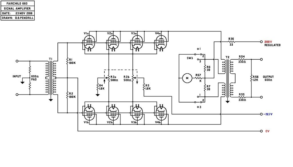
This is the signal amp:


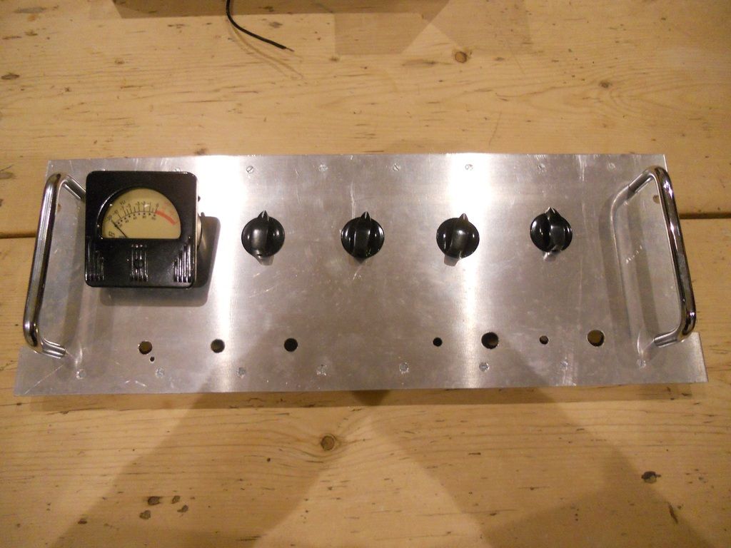
The values for R6,R7 & R57 will have to be chosen for the Sifam VU meter, I managed to get one before they ceased production of this vintage model.


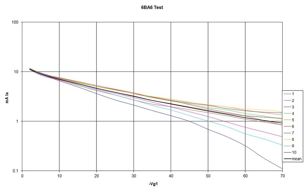
Some guys on this forum ran some tests of the 6BA6 versus the 6386 some time back, and the curves are a very good match.
I bought 20 x 6BA6 and easily found 8 that could be used together.  I tested each one's current down to -70V and drew a chart.
Here are the first 10 tubes.


I just averaged the data in Excel  (black trace), I was then able to eliminate the traces which were farthest from the mean until I got 8 tubes which when used on either side of the mean, balanced out nicely.

I believe that several compressor manufacturers make kits to sub the 6BA6 for 6386's so I'm on solid ground there.  Although there are 8 sockets to deal with, it's much cheaper to change one than a double triode at $99 a piece .

DaveP

 
Just out of interest, What are you using to test your tubes?

I've got a box full of assorted old tubes I'd like to test, But I don't have the budget for an Avo at the moment.
 
Lee,

I just made up an HT supply of 250V that I could keep constant as the current dropped, and a negative supply of just over -70V that I could also vary.  This was just a breadboard job.

I used a 10k anode resistor to measure the current.  then it was just a tedious task to measure each tube at -10V intervals and recording the figures to enter into excel.  If you have more time than money then it will work for you. ;)

Rob,
Unfortunately, CPC seem to have stopped supplying them, I bought about 5 of the large type before I retired and have been working my way through them, I think they came from India or the far east.  The part number was EN81256 and the manufacturer was unbranded, i.e. they didn't say.

I have decided to make them up with 15mm Al angle and 1.2mm sheet in future and pop rivet them together.  The amount of stuff I make does not justify a sheet bender.

Best
DaveP
 
Lots of detailed work on the chassis, it always takes a long while when the prototype has to be the finished article too.  Everything has to be thought out several steps ahead, which takes time.


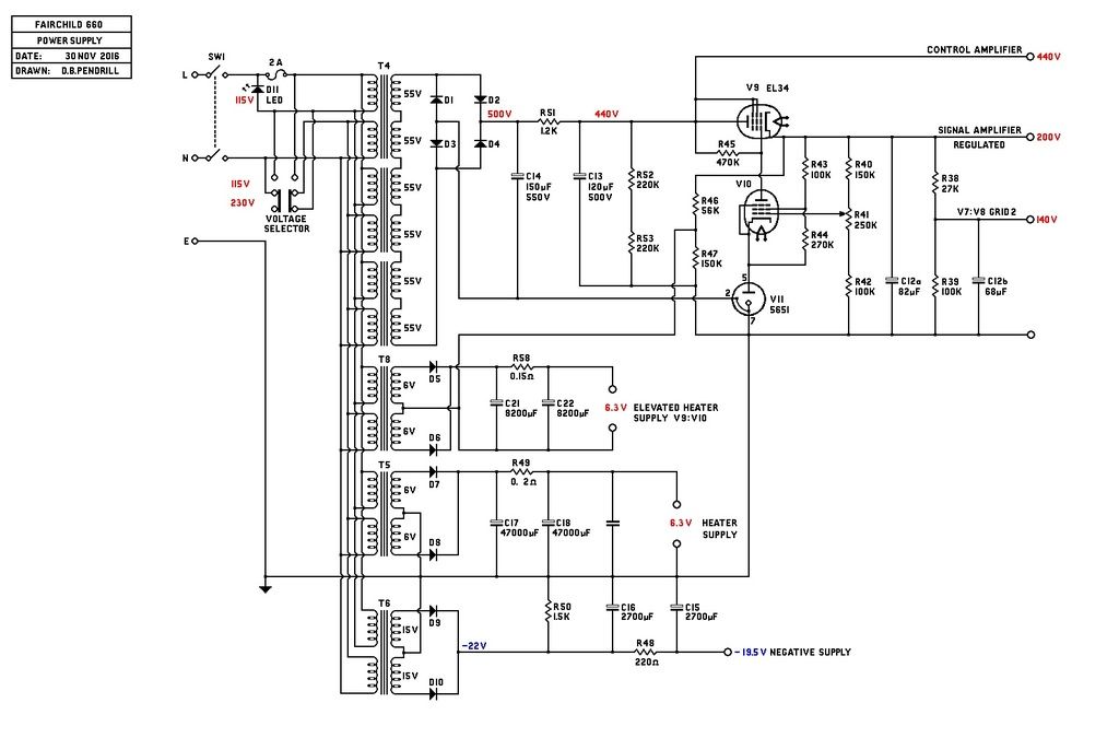
The box on the left will contain 6 toroidal transformers, these supply 500V B+ ,  a DC supply for the heaters and another TX for the elevated supply for the regulator.  There is also another for the 22V negative supply.

Power supply here.


Some people make 660's with solid state sections, but mine will try to copy the original circuit as far as possible, 15 tubes take a lot of heater current.  I have also included a voltage selector in case it needs to go to the US for some reason.  Following a recent debate here, I have also gone for a quieter LED indicator instead of a neon.

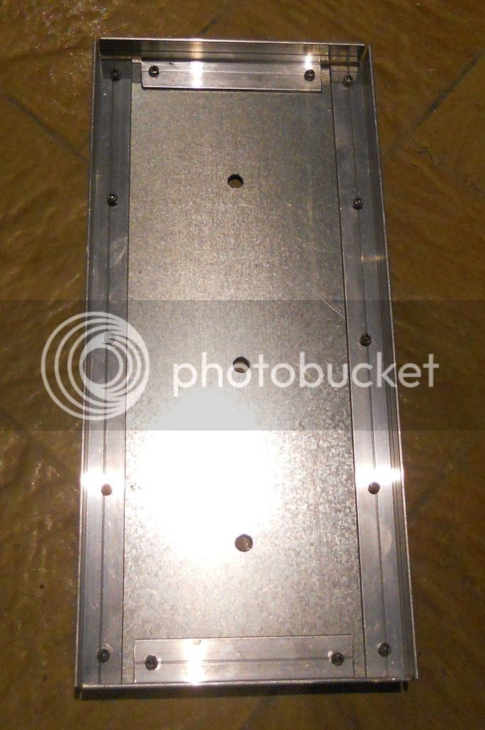
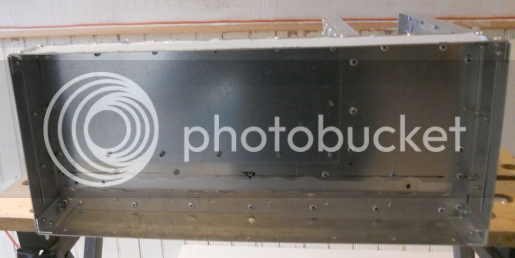
This shot shows the steel lining of the transformer box which should contain any stray fields from the toroids:


The main chassis is now almost finished, then I have to make the 4u front panel.

All for now
DaveP

 
Really nice project DaveP thanks for sharing with us, I will be following this thread with an happy smile.

Lee_M said:
Just out of interest, What are you using to test your tubes?
I've got a box full of assorted old tubes I'd like to test, But I don't have the budget for an Avo at the moment.

Tube testers can be quite expensive and need regulation and maintenance. It justifies to buy one if you work with tubes a lot, but for the "assorted old tubes" pack that you want to test once a year it doenst justifies the investment.

What I do is I have a friend that as the Orange VT-1000 Valve Tester and I made friendship with an older fellow that repairs and restores tube radios, he has an Hickok 6000A.
So normally once or twice a year I gather my "assorted old tubes" and I resort to a friend or the other to test all of them.

I would advise you to do the same, there should be someone near you that has a tube tester, that person might not even use it a lot and could lend it to you for some days.  You just have to find that person.

If you want to buy one I advise you to get the U tracer it's not crazy expensive and much more powerfull than conventional old tube testers:

http://www.dos4ever.com/uTracer3/uTracer3_pag0.html
 
If you want to buy one I advise you to get the U tracer it's not crazy expensive and much more powerfull than conventional old tube testers:

http://www.dos4ever.com/uTracer3/uTracer3_pag0.html

I just built one of these, it's really good, but there are somethings it doesn't do, so I won't be getting rid of the AVO mk IV.  If you want to match valves it's a great tool
 
Whoops said:
Tube testers can be quite expensive and need regulation and maintenance. It justifies to buy one if you work with tubes a lot, but for the "assorted old tubes" pack that you want to test once a year it doenst justifies the investment.

What I do is I have a friend that as the Orange VT-1000 Valve Tester and I made friendship with an older fellow that repairs and restores tube radios, he has an Hickok 6000A.
So normally once or twice a year I gather my "assorted old tubes" and I resort to a friend or the other to test all of them.

I would advise you to do the same, there should be someone near you that has a tube tester, that person might not even use it a lot and could lend it to you for some days.  You just have to find that person.

If you want to buy one I advise you to get the U tracer it's not crazy expensive and much more powerfull than conventional old tube testers:

http://www.dos4ever.com/uTracer3/uTracer3_pag0.html

Thanks for the suggestions!

I live in a fairly small town in a rural area, So meeting someone locally with a tube tester may be a challenge!  ;D
I also like the idea of being fully "self-sufficient" when it comes to having my own test gear and tools, So borrowing wouldn't be ideal in that sense.

A DIY tester is definitely an option I've thought about, I'd been considering building a sussex valve tester but it's not happened yet.

That uTracer unit looks interesting, but I'm a mac user so I don't think it will work for me...unless I can pick up an old windows computer for the bench.

@Rob Flinn - What were the limitations of the uTracer in your experience?

@DaveP - Sorry for hijacking your thread!
 
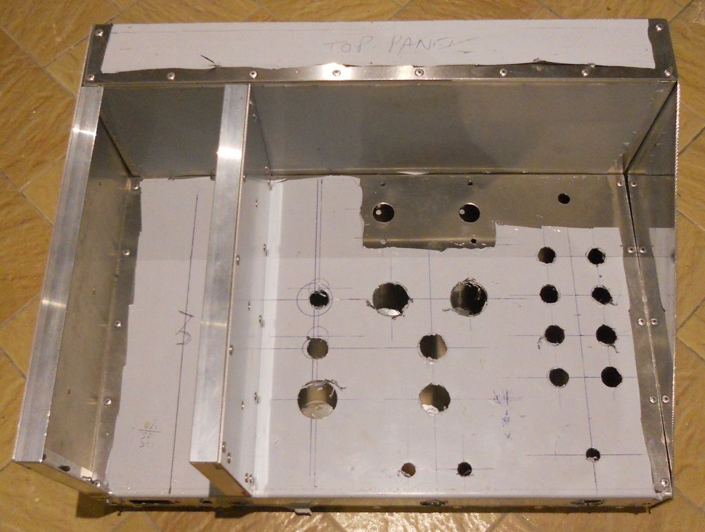
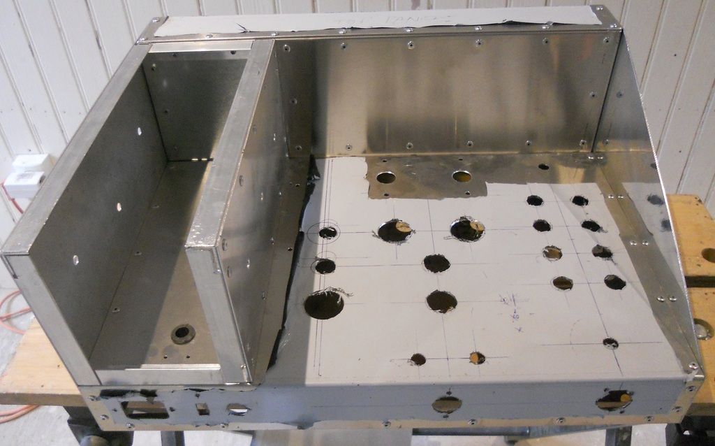
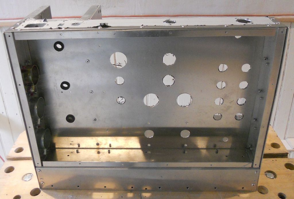
The main body of the chassis is now put together and built.
I have to fit the components now, starting with the tube bases.


Note the galvanised panel in the TX box to contain magnetic fields.

I have made a screen to go in here to hold some capacitors, it is an aluminium galvanised sheet sandwich.  I'm not sure it will be needed with toroidal transformers, but it would be too difficult to retro-fit later.


The front of the chassis also has a galvanised panel for shielding, but it's not coupled to the rest in the TX box.


I have left spaces to insert wiring  grommets to connect the front panel later on.

The whole structure is now very robust and solid and will easily take the weight of the internal components.  The original weighed 41lbs, I'll be keen to know what this one comes in as.  The front panel is 4u so it's the biggest chassis I've made to date, it goes back a long way in depth too.

Best
DaveP
 
Back
Top