Fairchild 660 from scratch

GroupDIY Audio Forum

Help Support GroupDIY Audio Forum:

This site may earn a commission from merchant affiliate links, including eBay, Amazon, and others.
WOW! Tha's the best Flux Capacitator I've ever seen.

Dave, could you possibly post a link or the type of that "dedicated red glue" you're using? I've been looking for something like this for quite some time but I don't even know where to look at (or what is actually called).
I do quite a lot of location recording and I'd like to use this for my builds.

Great job BTW!  :)
 
warpie said:
Dave, could you possibly post a link or the type of that "dedicated red glue" you're using? I've been looking for something like this for quite some time but I don't even know where to look at (or what is actually called).

Hi Warpie
Just google "thread lock", Loctite for example have extended product range.
Best
Zam
 
I get it from RS in UK

Part number 196-5245, its called "Tamper Evident Seal" for thread locking.

DaveP
 
No pics to show, but I fired up the finished circuits and all the voltages agree with the EMI report on the 660..............sigh of relief!
The only problem was that the feedback pair from the control amp tertiary winding were round the wrong way, quick re-solder and all was well.  Sods law dictates that negative feedback will always be connected up positively initially ::)

I can now finalize and fit the dropper resistor and move on to the front panel assembly.

DaveP
 
zamproject said:
Hi Warpie
Just google "thread lock", Loctite for example have extended product range.
Best
Zam

DaveP said:
I get it from RS in UK

Part number 196-5245, its called "Tamper Evident Seal" for thread locking.

DaveP

Thank you gents!

Dave, I was watching some videos (like this one) and it seems that only a little amount of thread locking is required. Is there a reason why you apply so much thread locking on each bolt?  Do you apply it to the actual thread as shown on the video or you just add it on top after you've fasten the nut?
 
Dave, I was watching some videos (like this one) and it seems that only a little amount of thread locking is required. Is there a reason why you apply so much thread locking on each bolt?  Do you apply it to the actual thread as shown on the video or you just add it on top after you've fasten the nut?
No, I don't apply it to the thread beforehand, it's too fiddly and messy to do that with small 3mm screws in confined spaces.  All the screws have spring washers already, so I just paint the remaining thread afterwards to make it difficult for the nut to come undone.  It's still possible to remove the nuts afterwards but much more force is required.

Best
DaveP
 
Although the amps all have the correct voltages, the first power supply cap hits 565V on switch on; this is a 550V cap so that will have to be changed for two series 350V caps with equalizing resistors.


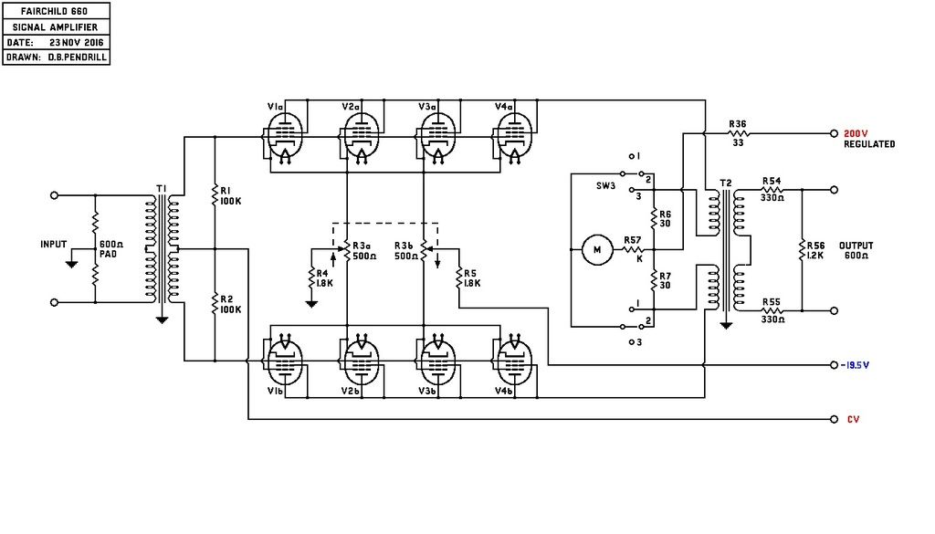
The original values  of resistors R6, R7 & R57 are not correct for the Sifam meter.  R6 & R7 have to be 51 ohms instead of 30 ohms  and R57 must be 120 ohms, this brings the meter to 0vu when the regulated supply voltage is correct.  The meter is slightly less sensitive than the original  (It's a $150 genuine vu meter by the way)

All for now
DaveP
 
DaveP said:
No, I don't apply it to the thread beforehand, it's too fiddly and messy to do that with small 3mm screws in confined spaces.  All the screws have spring washers already, so I just paint the remaining thread afterwards to make it difficult for the nut to come undone.  It's still possible to remove the nuts afterwards but much more force is required.

Best
DaveP

Thank you Dave.
 
beautiful what can i say Dave p  i hope my 670 looks like  that when finish,  by the way, what is the spacing between the 6babs  , looks like  they are  about 1cm apart ?

what is the reason for lowering the regulated voltage for the  signal amp plates.

regards

skal
 
Thank you,

The 6BA6's are in two lines of 4 tubes.

The centres of the tubes are 1.25 inches apart in the lines, but the lines are 1.5 inches apart.

The regulated voltage is set at 200V initially with new tubes.  The meter is set to measure the current at this voltage as a benchmark.

As the tubes age they draw less current, so the zero control allows you to wind up the voltage to compensate, so the current remains the same.

Best
DaveP
 
This is a truly inspiring thread..... to be honest, i understand very little of what you are all talking about. But , i can't wait to take this renown Compressor for a spin !!

I think Dave is a walking genius!  And a gent to chat with.
I say this as he has already built me a stunning sounding LA2A and a Pultec. (Which are used regularly , sometimes ahead of my other compressors like my Retro Sta Level).

I was in LA recording in December and the studio i was in had a vintage LA2A and Pultec and i was able to run a vocal through them (separately) and compare to Dave's units when i returned home, and they were almost identical in sound.

I dont know if my album project i am recording (for an artist on Interscope called Cloves) will be finished by the time it arrives, but this 660 might just make it onto the last song.

I've only ever used one 660 before in State of Ark studio's in Richmond London (and it didn't make everything sound like the Beatles) , but was very classy sounding indeed. And the compression was effortless / couldn't hear the compression.

Excited man here :)

Ian


No pressure then ;D

Ian is a very modest producer considering who he has worked with and I think this is one reason why he is in such demand.

I get my inspiration from the real geniuses on this forum.

Anyways,BTW.

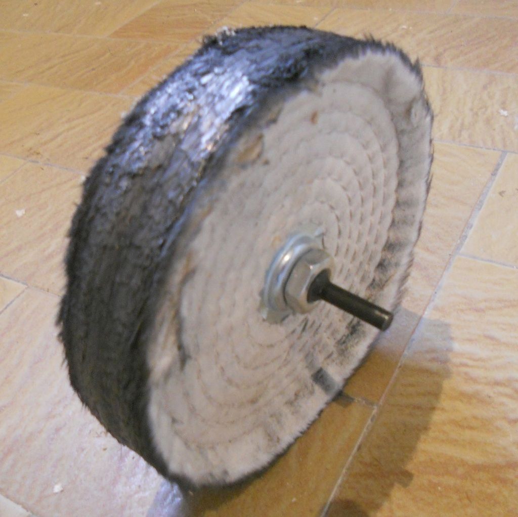
First, I buffed up the areas for the lettering to a mirror finish, there are three of them like the original 660.


Then I very carefully applied three sections of masking tape over these areas, where the lettering will be.

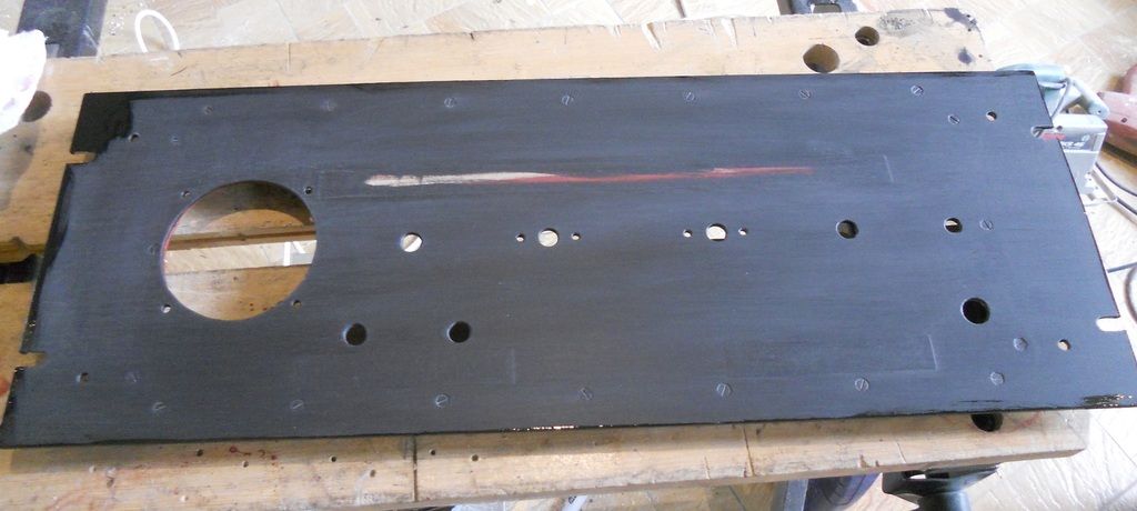
Once the masking tape was in place, I roughed up the rest of the surface with the scotchbrite pad from the kitchen (the wife has not seen that yet  ::))

Then I washed and dried the panel before giving it two coats of special metals primer (red).  I then rubbed this down with 1000 paper and then two coats of matt black with rubbing down between coats.


Here's the matt coat just about to have its coat of varnish.

I use this method because gloss black has far less opacity and covering power.


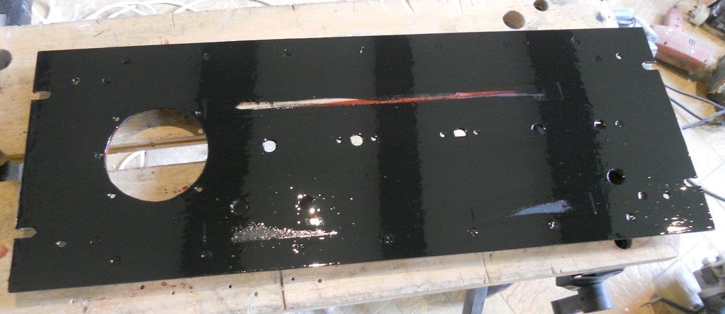
Here's the panel after varnish, a nice gloss finish.  The three black bars are reflections of the ceiling beams!

Lettering next tommorow,

DaveP
 
Hi Dave p


sorry to bother you again , just wanted to know wot gauge of wire you are using for the power B+ and heater filament for the signal amp and control amplifier , are stranded or solid, also what type are using for signal lines...

cheers

skal1
 
This is the stuff, from RS in various colours
http://uk.rs-online.com/web/p/hookup-equipment-wire/7482250/

Best
DaveP
 
I have more time to answer now.

The wire is 24 stranded and it's tinned.  Tinned is best for long term use as straight copper gradually gets a sulphide coating over time.

I use two sorts for signal wires.

For single core I use a plaited tinned coaxial with low capacitance from CPC in the UK and for balanced signals I use Van Damme tour grade mic cable.

DaveP
 
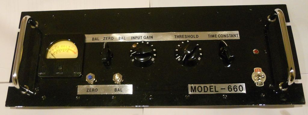
Finished assembling the front panel components.


Lit the meter with a concealed battery.

Before final assembly I have to fit all the timing components on the inside plus the meter circuit and signal cables.

DaveP
 
DaveP said:
I have more time to answer now.

The wire is 24 stranded and it's tinned.  Tinned is best for long term use as straight copper gradually gets a sulphide coating over time.


DaveP

so what gauge is 24 24 stranded  ?

cheers

skal
 
Follow the link I gave earlier, here it is again:-
http://uk.rs-online.com/web/p/hookup-equipment-wire/7482250/

Then go to the right where it says technical Reference, then download the pdf.

DaveP
 
Back
Top