Fairchild 660 from scratch

GroupDIY Audio Forum

Help Support GroupDIY Audio Forum:

This site may earn a commission from merchant affiliate links, including eBay, Amazon, and others.
I'm now able to start fitting the components.
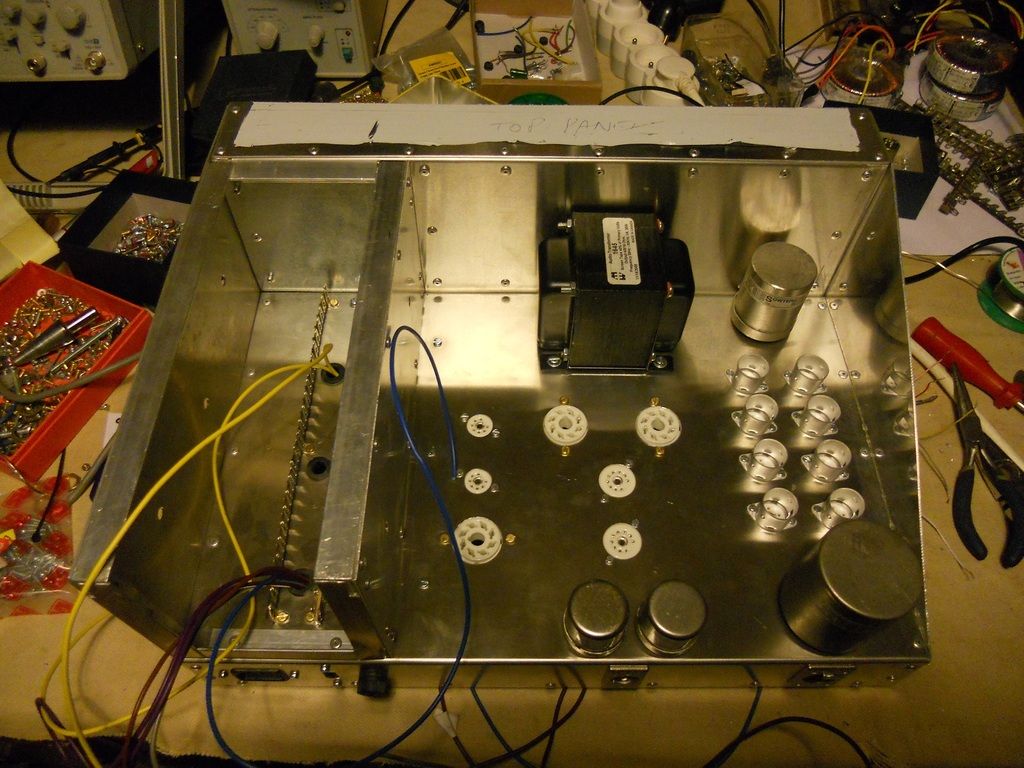


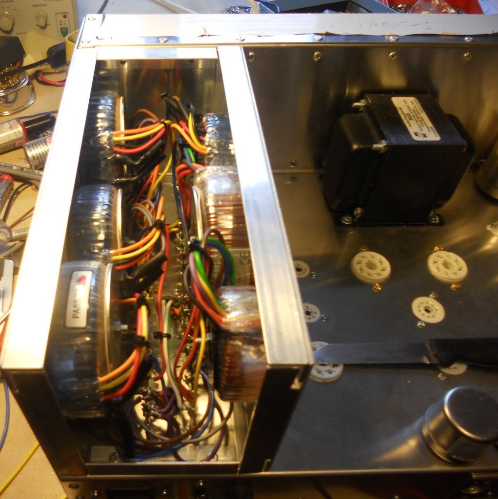
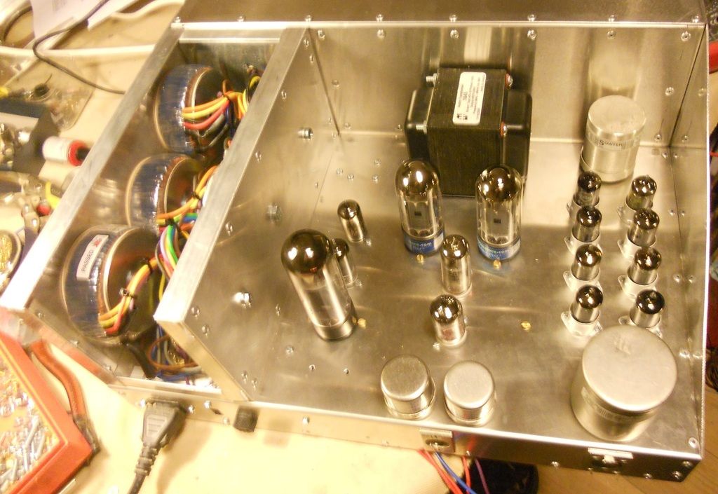
The Sowter input and output transformers and the 8 bases fpr the 6BA6's are on the right.

The TX's for the control amp are not so critical so I used a pair of OEP's and a big 30W Hammond 1645.

The bases on the left are for the EL34 passing tube, a 6AU6 and a 5651, all part of the regulator.
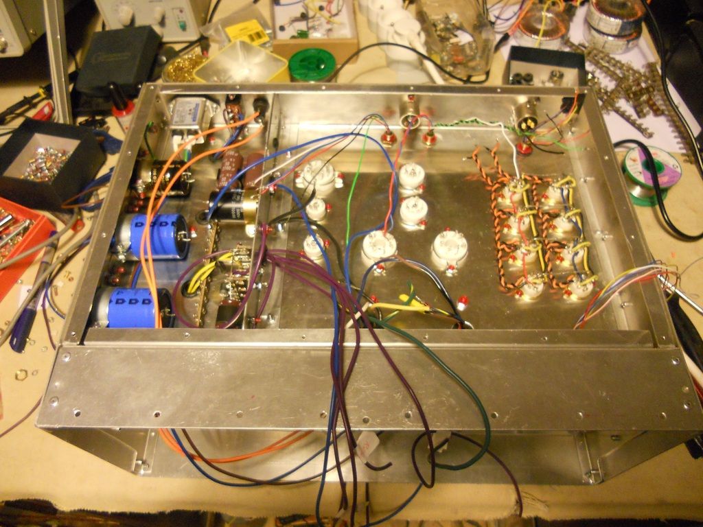


It took some time to design the power supply compartment, but all the capacitors are in place now.

I have been marking up the schematic as I go with the colour codes for the wiring.  with such a big amp, you could easily forget what's what, by the time you got around to connecting something later.

Over the next week I hope to wire up the heaters and put in an earth busbar following Merlin Blencowe's online advice.

I have used a mains voltage selector switch for the first time, this complicated the power transformer wiring considerably, but is worthwhile on a top-end compressor.

All for now.
DaveP
 
Every now and then, my wife brings one of her friends to look at the big silver box on my desk with dozens of wires poking out of it.

Today they said "What is it you're making"?  Like an innocent I said, it's a Fairchild 660.

But what does it do they asked................?

Like a fool I said "It compresses sound".

Then drawing on rare feminine insight going back 30 years, they announced,

"It's a Flux Capacitator".

The mockery continues....how we suffer for our art ::)

DaveP

 
DaveP said:
Every now and then, my wife brings one of her friends to look at the big silver box on my desk with dozens of wires poking out of it.

Today they said "What is it you're making"?  Like an innocent I said, it's a Fairchild 660.

But what does it do they asked................?

Like a fool I said "It compresses sound".

Then drawing on rare feminine insight going back 30 years, they announced,

"It's a Flux Capacitator".

The mockery continues....how we suffer for our art ::)

DaveP

:)  I know exactly what you mean.  :D ;D ;)    Great thread!
 
DaveP said:
Every now and then, my wife brings one of her friends to look at the big silver box on my desk with dozens of wires poking out of it.

Today they said "What is it you're making"?  Like an innocent I said, it's a Fairchild 660.

But what does it do they asked................?

Like a fool I said "It compresses sound".

Then drawing on rare feminine insight going back 30 years, they announced,

"It's a Flux Capacitator".

The mockery continues....how we suffer for our art ::)

DaveP
This puts a smile upon my face because it's so recognizable..  8)
 
Glad to hear there are other husbands out there who share my experience ;D

The hard part first:-

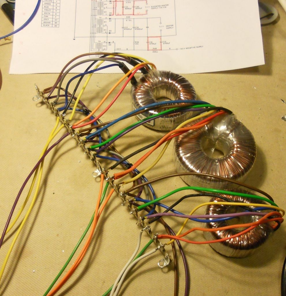
I had to wire up the toroids  in sub-assemblies before mounting them in the box.


This is a prototype, so you find out all the snags, I should have made the box about an inch wider but it would have made the rest to the amp a bit cramped, so never mind.


I have almost finished the power supply now, only the B+ rectifiers to site.  I have also fitted the first busbar onto which all the others will connect.  It is not connected at the power inlet, it's connected to chassis at the input socket a' la Merlin.


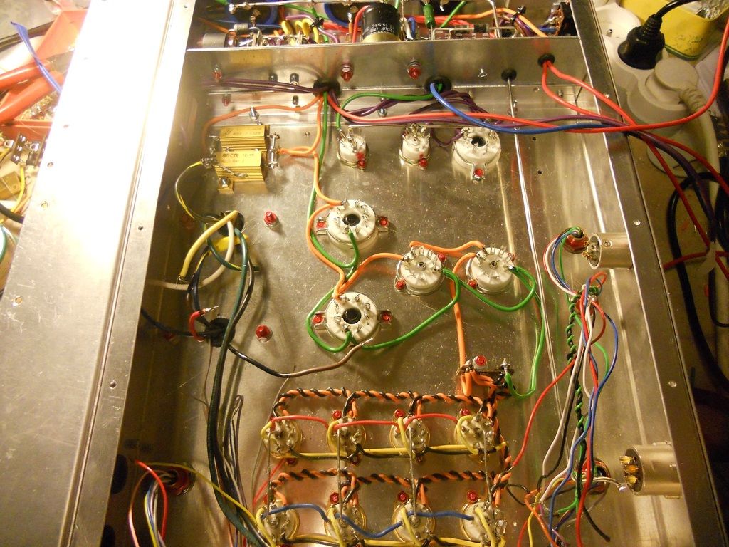
The next stage is to wire up all the heater supplies, so that I can fit the tubes and check the heater voltages.  I have to find the correct dropper resistance for the DC heater supply and this is the only way to do it.  I will also have to do a similar test for the B+ supply, but that needs the entire amp finished for that test.

I have colour coded all the wiring on the schematic, it's the only way to keep track of where everything goes on a project this size.

DaveP
 
DaveP said:
Every now and then, my wife brings one of her friends to look at the big silver box on my desk with dozens of wires poking out of it.

Today they said "What is it you're making"?  Like an innocent I said, it's a Fairchild 660.

But what does it do they asked................?

Like a fool I said "It compresses sound".

Then drawing on rare feminine insight going back 30 years, they announced,

"It's a Flux Capacitator".

The mockery continues....how we suffer for our art ::)

DaveP

Great Scott! 1.2 Gigawatts!

It's looking fantastic so far Dave!
 
Thanks Rob,

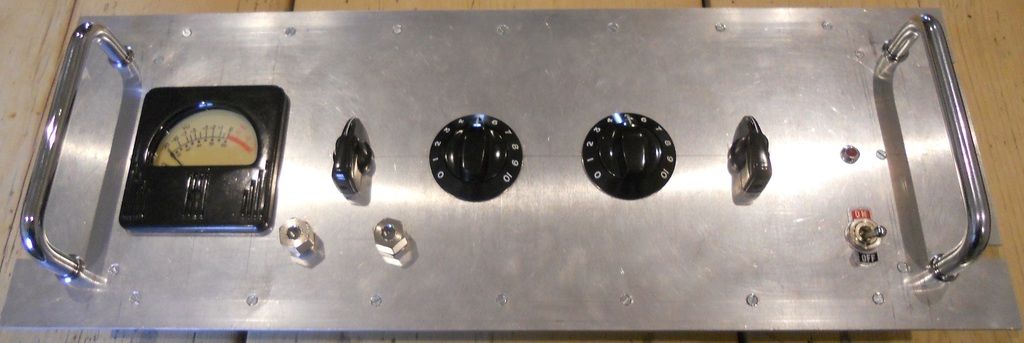
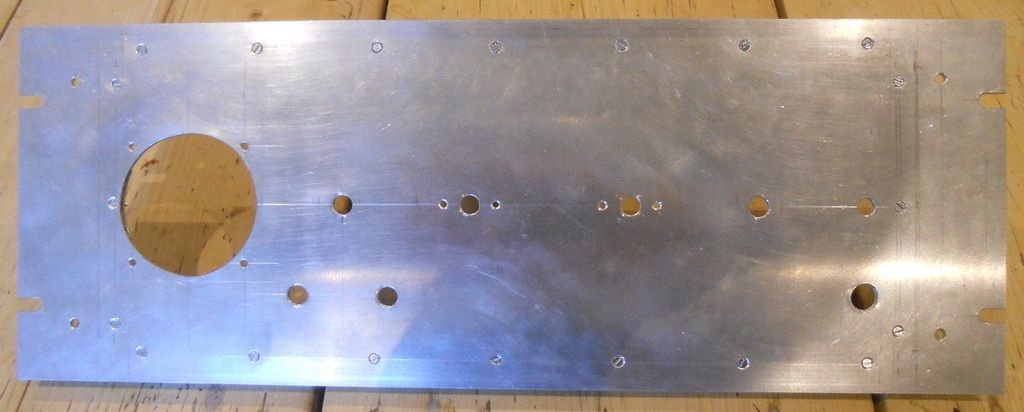
Sunday was a day of careful measurements, drilling and filing of some 3mm plate from RS.

And this was the result:-


I can't pretend that was easy, you can't afford to make any mistakes or scratch the surface, so I covered it up with masking tape while I was working on it.

I recessed the countersunk screws by using a drill with a just slightly larger diameter than the head width.

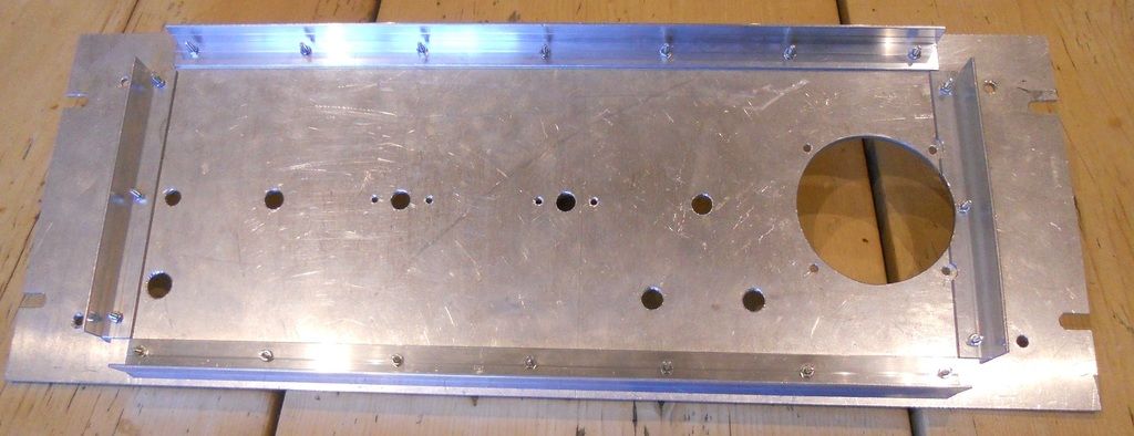
There are 20 screws holding on the angles which hold the weight of the amp in the rack.


This is what I am aiming for, the original 660 faceplate.


This is not a full rack panel as it sits in another box for that purpose, my design uses the full width so there is more room available.  I have used exactly the same layout, except that all my amps have the on/off and indicator on the right hand side.

With the components added, you can see that the controls will be exactly the same.


I still have to work out the paintjob, but hopefully it will do it justice.

DaveP
 
Well Leo, you may have to wait a little longer, but we are getting there.

I finished the heater wiring to the main amp and the elevated heaters in the regulated supply, all the Al clad resistors are now in place.  As the heater voltage is all DC right through the amp, I have not bothered with twisting it, except for the signal amp and that is just a belt and braces decision, to make absolutely sure for the lowest S:N ratio.


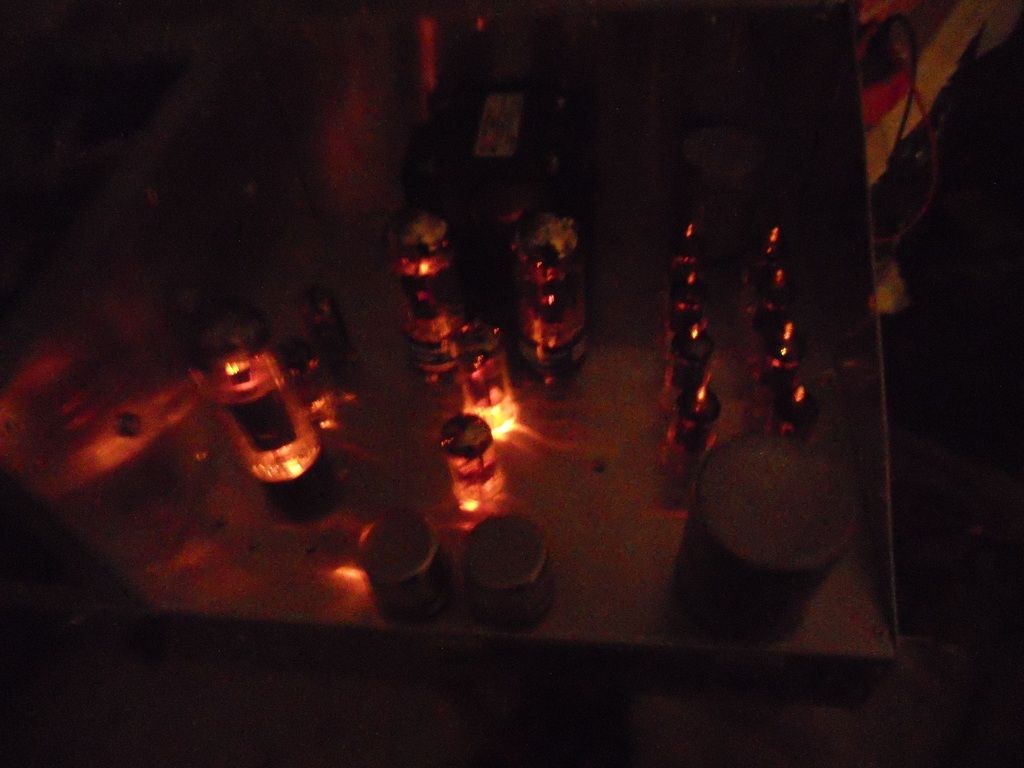
I had to get all the tube heaters working for this.  There they are, all 15 of 'em.  The 6V6's are a matched pair.

.

Just so you know they are lit up.

.

Now I can start the interesting part................point-to-point wiring.

DaveP
 
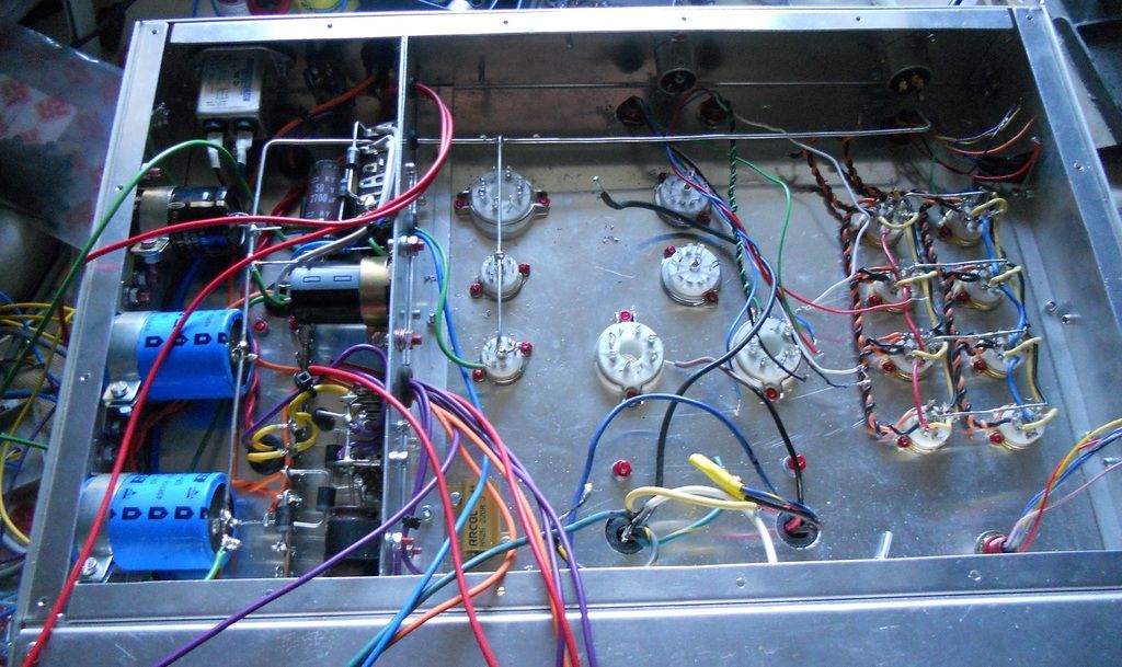
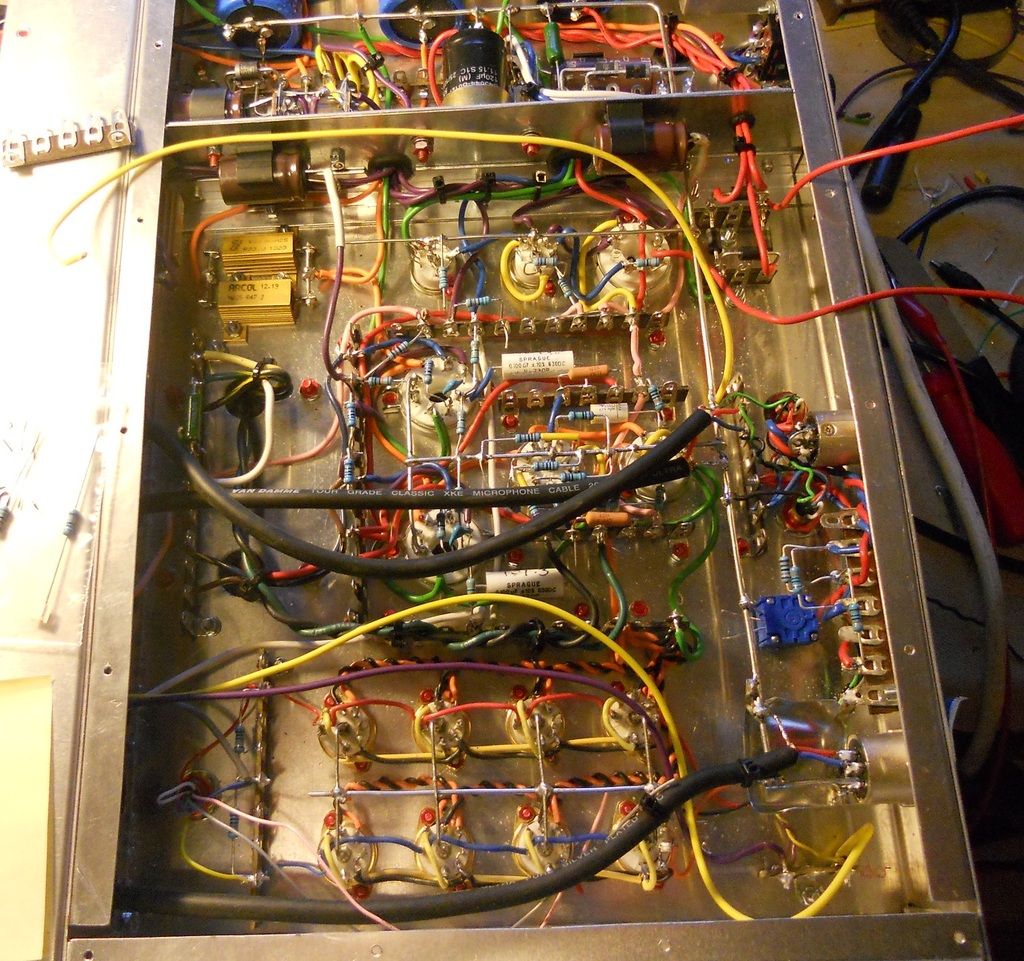
I have been building the various parts of the 660.

Lots of of careful painstaking soldering etc.


The very top section is the power supply compartment.  Below that is  the regulated supply.

Below that is the control Amp.

The lowest section is the signal amp.

The next part involves firing it up to settle the value of the B+ dropper resistor to get 440V, this has to be done live.

I can check all the voltages at the same time and check for smoke!!

I have yet to tidy up the wiring, you can see the mic cable going through to the front panel.  This goes to the threshold control on the front panel and returns back to the control amp.

There are lots of wires going through to the front and returning, and they all have to be thought of in advance.  I also colour code the schematic at the same time, for any one who might need to overhaul the 660 after I'm gone.  All the caps are high quality long life types so I don't think they will need touching for at least 10,000 to 20,000 hours of continuous use.

best
DaveP
 
Dave, why are you painting the bolt threads and nuts?  Is it to seal them in place?  Are you sure no one will ever want to dissemble those parts, maybe you?

Marvelous build and great inspiration.
 
tommypiper said:
Dave, why are you painting the bolt threads and nuts?  Is it to seal them in place?  Are you sure no one will ever want to dissemble those parts, maybe you?

Marvelous build and great inspiration.

Hi
It's not paint but dedicated glue, and yes this is thread lock, it's a common practice, there is various firmness available, I believe Dave use one which allow unmounting.
Best
Zam
 
Yes, that's right.

I ship my stuff to other countries so it prevents nuts and bolts coming undone due to vibration on long journeys.

Some old 50's 60's 70's gear even used to paint over soldered joints to prevent deterioration, I use lead-free flux for new builds and that is almost pure tin so less chance of oxidation.

DaveP
 
Back
Top