Fairchild 627 from scratch

GroupDIY Audio Forum

Help Support GroupDIY Audio Forum:

This site may earn a commission from merchant affiliate links, including eBay, Amazon, and others.
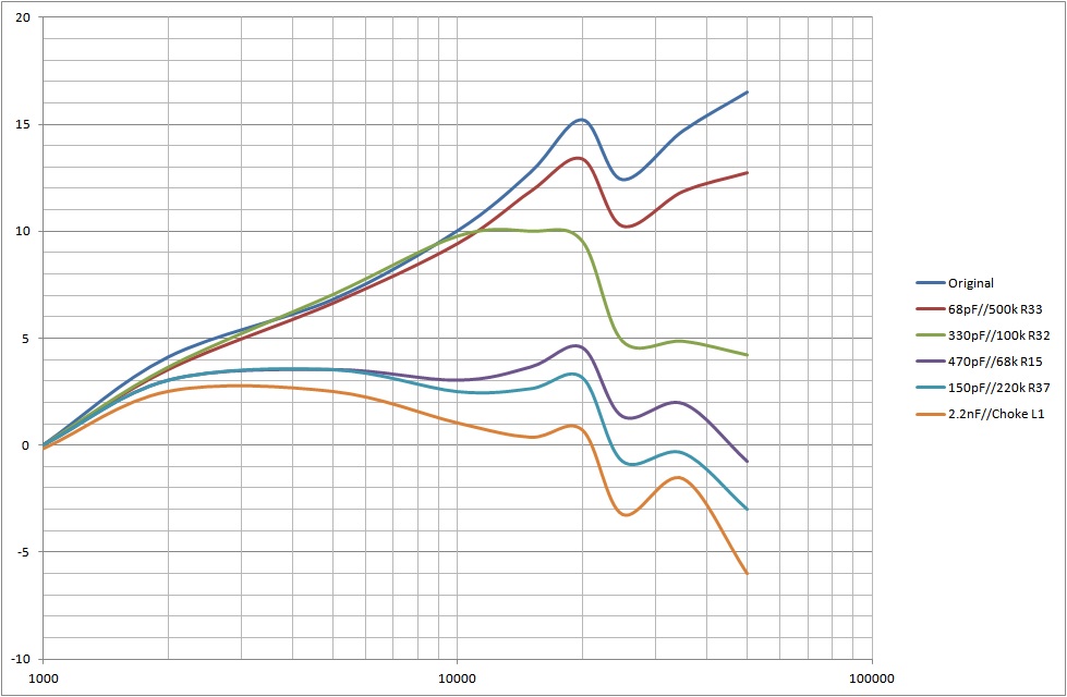
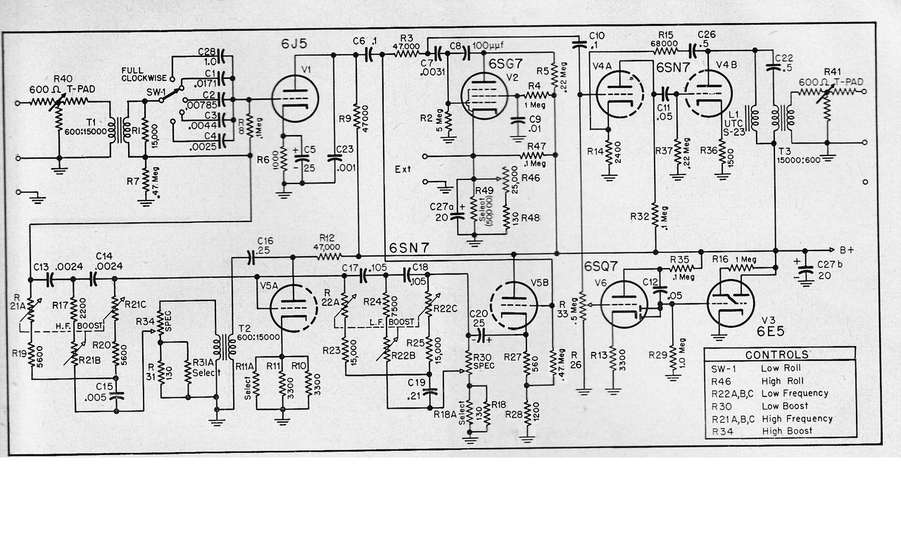
After testing the frequency response of the whole equaliser, the 4.4nF cap was removed because it gave too much top-end. My conclusion is that the overall circuit has a rising high frequency response which the output stage needs to reduce to get back to a flat overall response.

I have attached my final schematics. While I have been using the 627, I noticed that it uses quite low input levels due to the IPT ratio and V1's operating range. I also had to be careful about levels when testing the boost; if you don't allow for the increase in level then you can end up with distortion. There can also be a distortion problem if the level is too low, the boost circuits are a complicated feedback circuit and I noticed 20Hz distortion if there was not enough NFB. I still have some charts to produce before I sign-off the project and I will give some suggestions about maximum and minimum input and output levels as well.

Best
DaveP
 

Attachments

  • 627 Final Schematic.jpg
    627 Final Schematic.jpg
    1.1 MB · Views: 8
  • 627 Power Supply.jpg
    627 Power Supply.jpg
    79 KB · Views: 2
I have hit a problem that I would like your advice on.

There is a resonance at 51kHz and another at 23kHz.

This results in high roll-off curves that look like this:-


I have not extended the frequency response to 51kHz but the peak has a similar height to that at 23kHz but obviously could not be heard.

I suspect that the resonances are caused by the Edcor 15K:600 transformer in the feedback loop. This is difficult to counter because in the feedback loop, any cap which shorts these frequencies within the loop has the opposite effect. It reduces negative feedback, in effect giving a boost.

Looking at the original schematic:-


I believe the only place that a cap can be used is where the NFB is injected is at R7 the 470K resistor. Please note that there is a cap C23 of 1nF which reduces the high frequency response of V1, this could possibly be increased a little.

The problem is complicated because 23kHz is very close to the 10KHz boost and any corrective measures could affect this boost.

I have used a 500Hz square wave to identify the feedback loop as the source of the problem

I hope I have explained the problem clearly and that some of you have some useful ideas.

In the end it would probably not affect the sound of the box but it is not good engineering to allow problems like this to go untreated.

Best
DaveP
 
Hello Dave just an idea can you not use a Notch filter at those frequencies to make it flat? I know it does not tame the route cause but why would you not do that? It was often used to get a flat response in many pieces of professional equipment if I recall rightly so the whole chain was flat......

Best Steve
 
Hi Steve,
Thanks that is a good idea to try, I was also thinking of trying a tank circuit for the same effect.

Best
DaveP
 
Sorry I haven't read this thread at all up till now so I may have missed important bits but ...

Do you have that 300H inductor equivalent to L1 in your circuit?

Was the OT loaded with 600 ohms when you took the measurements?
 
Hi Bo Deadly,
The inductor L1 is in the circuit and the OPT is loaded with 600 ohms.

At first I thought it was the output stage, but changes here only reduce the amplitude, I need to address the source where the frequency can be changed. See attachment

DaveP
 

Attachments

  • Damping Ringing in LC Circuits.pdf
    268.2 KB · Views: 4
I am still no closer to finding a cure for the problem but I have learnt a lot about the 627 design in the process. I have reduced the 52kHz peak by 48dB with a notch filter but this has effects on the audio spectrum as well. If I use a notch filter on the 23kHz peak, then I get a peak at 15kHz instead. It is as if there is some energy in the system that is determined to come out somewhere! The problem is complicated because the high boost control does not go down to zero at any frequency, so the peaks can be affected by whether the control is at 10kHz or 4Khz even when the boost is on 0dB.

I have been working on this for weeks and I find it a greater challenge than the UE-100 I made 2 years ago. The problems with the UE-100 were because of my own errors, whereas these are because of the complexity of the 627 design. If you think about the amount of NFB and the phase shift in the design, then extra capacitance at ultra sonic frequencies can cause negative feedback to become positive. I think that this is the mechanism that is making peaks appear at other parts of the spectrum. In some ways I am reluctant to make changes to the circuit to correct what are just ultra sonic effects but they nevertheless cause ringing on transients.

I will persevere! But this is not a beginners project.

Best
DaveP
 
Some observations about the 627.
I read that only 5 were ever made.
Perhaps it's not the most intuitive equaliser to operate, but I would be interested to hear how other users find it.
I think maybe it needs an artistic approach; to move dials and to see what happens. This approach should provide a rich range of sounds and plenty of unexpected results!

I am making progress on tidying up the response curves and will post them shortly.
Best
DaveP
 
After trying many different strategies, I settled on correcting the output amp V4ab. I found that modifying the feedback loop around V1 caused too many secondary problems.

In the following chart I show what various bypass capacitors do to the frequency response.
All the -3dB points are set to 5kHz.

I welcome your comments about which to retain.


Best
DaveP
 
What are you feeding the circuit with?
Source Z etc..

Have you investigated the response of each transformer separetley with nominal source/Load Z?
 
Hi 5v333,

I am feeding the IPT with the 600 ohm output from my signal generator. The secondary is already loaded with 15k.

I have been using Edcor transformers for years without problems, so I have not checked them this time.

DaveP
 
I would isolate some parts of the circuit and investigate them separately. If one part has a funny wigglness id see If I could strightn it out and then see how the whole circuit acts.

The output of the feedback network for ex and v2.

It would prob lead to more understanding of things aswell.

Maybe you have already done this for some time...
 
Hi 5v333,

Thank you for your advice.

I suspected the 10k input pot might be a poor match so I tested the output from T1 with it in place. This is the rising blue trace.

This just makes things worse so I changed it to a 500 ohm pot which is a very good match for 600 ohms. This is the completely flat red trace

Next I tested the output from V1 at C6, this shows that the NFB loop around V1 has this peak at 25kHz. This is with all controls on minimum but the peak selection on 10KHz as in the Fairchild charts.

The green trace is with the new 500 pot in place.


I think you can now see the scale of the problem. Every time I tried to modify this peak it just showed up somewhere else; this is why I have been modifying the output stage.

Any ideas?

Best
DaveP
 
My signal generator went into the input socket. I recorded the level from the oscilloscope at the place under test. I took readings at 1k, 2k, 5k, 10k, 15k, 20k, 25k, 30k, 40k, 50k, then I put them into Excel and converted them to dB ref 1kHz.

Best
DaveP
 
I expect that you have a fault somewhere... if you do it correctly your "flat" frequency response should look fairly similar to the original.

Here is the ez627 vs our original unit.

Green is our original, Cyan is the ez627.

ez627_vs_original_fairchild_freq_response.jpg


Colin
 
This is the response from the entire circuit without the nfb connection to R7/R8
The falling response is due to C23 shunting V1 I guess


I will try to get rid of the resonance around 50k before I re-connect the feedback circuit

Best
DaveP
 
Back
Top