You are using an out of date browser. It may not display this or other websites correctly.
You should upgrade or use an alternative browser.
You should upgrade or use an alternative browser.
Fairchild 627 from scratch
- Thread starter DaveP
- Start date


Help Support GroupDIY Audio Forum:
This site may earn a commission from merchant affiliate
links, including eBay, Amazon, and others.
5v333
Well-known member
You could look at the response of the output of the feedback while your at it just to know what is there and what is not there.
My only intentions are to keep you investigating.
My only intentions are to keep you investigating.
I have tested the frequency response on R14 as suggested and I also tested it with 47pF in // with the feedback resistor R15.
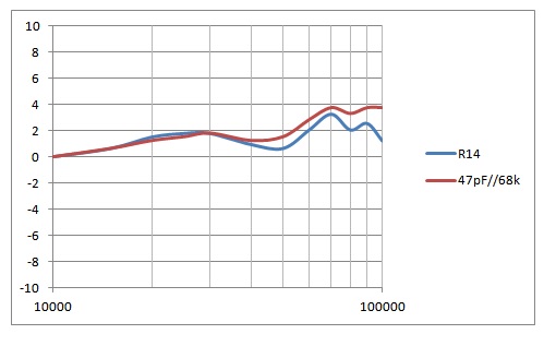
I think that this shows that there is a phase reversal at around 40kHz and the feedback becomes positive, hence the boost.
What do you think?
DaveP
I think that this shows that there is a phase reversal at around 40kHz and the feedback becomes positive, hence the boost.
What do you think?
DaveP
5v333
Well-known member
Hi.
Im having exams this week, so im rather occupied.
Im not following 100% with how you interpret your measurements. I would use two probes and look at the input and output of a perticular part.
Since AV = u_out / u_in.
But if you have a hunch where a problem lies then experiment with it.
now i gotta go back and learn 50 definitions and theorems until friday...


$15.98
$16.98
Gikfun Upgraded USB Mini Amplifier Electronic Transparent Stereo Speaker Box Sound Amplifier DIY Kit for Arduino EK1918
Gikfun_Official_Store


![Soldering Iron Kit, 120W LED Digital Advanced Solder Iron Soldering Gun kit, 110V Welding Tools, Smart Temperature Control [356℉-932℉], Extra 5pcs Tips, Auto Sleep, Temp Calibration, Orange](https://m.media-amazon.com/images/I/51sFKu9SdeL._SL500_.jpg)


Let us hope that 5v333 remembered all his definitions today.")
Having found that the ultrasonic problems come from the output stage, I have concentrated on discovering exactly where they arise.
All the response curves were referenced to 0dB at 10kHz to make life easier.
First of all, I tested the output transformer unpowered in/out, this is the blue trace. This shows that there is rise from 30-60kHz due to resonance. The OPT secondary was loaded correctly with 600 ohms.
The red trace is the whole output stage powered with B+ HT, this shows that the trace follows exactly the same curve as the OPT, slightly modified by the nfb.
In an attempt to reduce the ultrasonic response I connected a 47pF cap between the anode and grid of V4b, this is the green trace.
The purple trace is as the green trace but with 100pF between the anode and grid of V4a. It is interesting to note that at 70kHz there is a slight phase reversal but then the response drops dramatically.
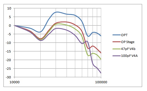
Best
DaveP
Having found that the ultrasonic problems come from the output stage, I have concentrated on discovering exactly where they arise.
All the response curves were referenced to 0dB at 10kHz to make life easier.
First of all, I tested the output transformer unpowered in/out, this is the blue trace. This shows that there is rise from 30-60kHz due to resonance. The OPT secondary was loaded correctly with 600 ohms.
The red trace is the whole output stage powered with B+ HT, this shows that the trace follows exactly the same curve as the OPT, slightly modified by the nfb.
In an attempt to reduce the ultrasonic response I connected a 47pF cap between the anode and grid of V4b, this is the green trace.
The purple trace is as the green trace but with 100pF between the anode and grid of V4a. It is interesting to note that at 70kHz there is a slight phase reversal but then the response drops dramatically.
Best
DaveP
5v333
Well-known member
Hi Dave. Both exams this week went fine. Subatomic physics next!
See if you can strightn out the response with a zobel across the OT sec.
See if you can strightn out the response with a zobel across the OT sec.
5v333
Well-known member
Me and the phonons wish you good luck
I have finally tamed the beast after 3 months work.
In the chart below we see the green trace with the nfb connected and no other additions, this shows the uncontrolled resonance due to the OPT.
The blue trace shows the response with a 22nF cap across the OPT secondary, this follows the advice of 5v333 which has proved to be very useful. I tried other values either side of 22nF but the results were worse.
The red trace is as above but also with a 1nF cap across R9 on V1, this moves the peak down frequency and makes possible the next change.
The final yellow trace adds a 27pF cap across R32 on V4a. This gives a flat response from 10Khz to 20Khz which was the original objective.
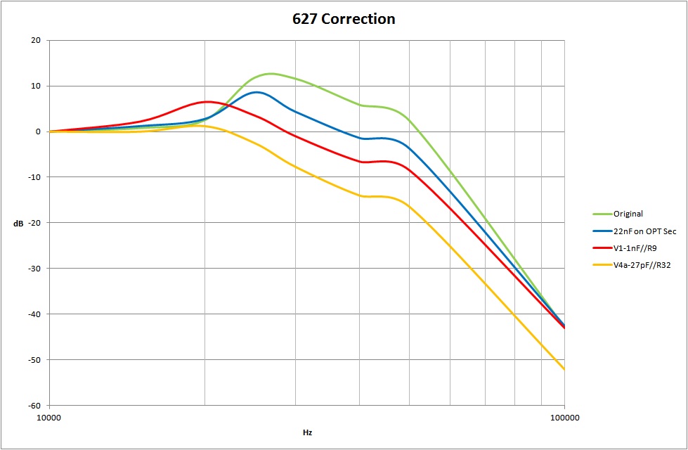
I hope that this exercise has encouraged fellow members to persist with their projects, it also shows that the advice of others members can provide very useful ideas to break the log-jam, like disconnecting the nfb loop from 5v333.
Best wishes
DaveP
In the chart below we see the green trace with the nfb connected and no other additions, this shows the uncontrolled resonance due to the OPT.
The blue trace shows the response with a 22nF cap across the OPT secondary, this follows the advice of 5v333 which has proved to be very useful. I tried other values either side of 22nF but the results were worse.
The red trace is as above but also with a 1nF cap across R9 on V1, this moves the peak down frequency and makes possible the next change.
The final yellow trace adds a 27pF cap across R32 on V4a. This gives a flat response from 10Khz to 20Khz which was the original objective.
I hope that this exercise has encouraged fellow members to persist with their projects, it also shows that the advice of others members can provide very useful ideas to break the log-jam, like disconnecting the nfb loop from 5v333.
Best wishes
DaveP
5v333
Well-known member
Yeay!
When i work with zobels i put a cap and a pot in series with aligators.
I hook this net to the transformer and probe pre(perhaps pre the amp driving the transformer) and post with a scope and a sweepable generator.
I then observe the freq response, phase response and a steady square wave at about 5khz.
The square might have a significant overshoot.
I try to get the freq/phase response as smooth as i can with out ringiness and at the same time get a squarewave that looks like a square wave.
The pot helps me tune in the offending resonance. I begin with smaller caps like 470p and increase if tuning with the pot didnt get me all the way.
This i have done with IT´s and OT´s.
5v333
Well-known member
Hi-fi... ve!
Hello Dave, thanks for a lot of information and ideas!!! I was also able to (almost) complete my pair of 627 EQs. A bit about my setup: I used Igor's UTM Transformers (fabulous!) for the build. The frontpanel is from Franks frontpanels.de with UV printing on anodised aluminum - with a touch of "crackle coating" imitation. The tubes (most are matched) and the power supply are from BTB Electronic Germany, the power supply is unregulated - heavily based on your power supply schematic - thx man. I used 600 ohm T-Pad pads for input and output, the triple turn/gang frequency pots are 24 step switches - I have decided this is the easiest way for me to clone the originals this way. But it is certainly not "fully variable". As for the audio path I took Colins and also the original schematic to build the circuit. Unusually I built it on circuit boards to hold the tube sockets. These prevented me from making mistakes when building stage by stage without losing control of this really complex build. And yes, it worked pretty well for me. I grabbed two Soviet 6E5s Magic Eye Tubes. But the seller cheered me on an old worn tube, light power is nearly gone, the other works as new  ....
....

Everything works great, I had no real issues with the setup. One little thing was with the original C27B cap which caused a 13Hz hum. I replaced with a higher one, thats it. No hum at all, very low noise. As Dave described the headroom is limited. My frequency response which I checked "quickly" with the audio card looks good linear in a range of 2.5 dB range from 20-20K, all filter curves are looking good and working as expected. I use two Hammond 156c on the Output TX to get a nice Lowend. With the extra 130 ohms across R18A and R31A to ground I can get a maximum gain of around 13-16dB depending on the frequency range of the Hi and Low Band. Booth units are very matched with all curves and the frequency response are also very close.
It sounds absolutely fantastic, super class. Really different than a passive Pultec. Not as sweet. It rocks, broad, 3D, sexy, it has character.
Btw I would suggest this build to real masochists only. Not a lot money to save compared to Colins, really lots of time consumption, lots of time for studying the schematics, searching for components, building, improving, setup..... I think Colin has really a good Kit on the start. My opinion.
....Everything works great, I had no real issues with the setup. One little thing was with the original C27B cap which caused a 13Hz hum. I replaced with a higher one, thats it. No hum at all, very low noise. As Dave described the headroom is limited. My frequency response which I checked "quickly" with the audio card looks good linear in a range of 2.5 dB range from 20-20K, all filter curves are looking good and working as expected. I use two Hammond 156c on the Output TX to get a nice Lowend. With the extra 130 ohms across R18A and R31A to ground I can get a maximum gain of around 13-16dB depending on the frequency range of the Hi and Low Band. Booth units are very matched with all curves and the frequency response are also very close.
It sounds absolutely fantastic, super class. Really different than a passive Pultec. Not as sweet. It rocks, broad, 3D, sexy, it has character.
Btw I would suggest this build to real masochists only. Not a lot money to save compared to Colins, really lots of time consumption, lots of time for studying the schematics, searching for components, building, improving, setup..... I think Colin has really a good Kit on the start. My opinion.
Attachments
-
 PXL_20230424_193431030.jpg2.1 MB
 -
 PXL_20230424_193850710.jpg3.2 MB
 -
 image.jpg945.4 KB
 -
 PXL_20230415_080933690.jpg2.1 MB
 -
 PXL_20230423_145615374.jpg2.7 MB
 -
627 Audio Test.mp424.2 MB
-
 PXL_20230424_195421271.jpg1.1 MB
 -
 PXL_20230425_200605643.jpg1,003.5 KB
 -
 PXL_20230424_195641253.jpg1.1 MB
 -
 PXL_20230424_200816658.jpg1 MB
 -
 PXL_20230424_200511808.jpg956.6 KB
 -
 PXL_20230424_195601503.jpg1.1 MB
Last edited:
Similar threads
- Replies
- 10
- Views
- 736
- Replies
- 1
- Views
- 424
- Replies
- 4
- Views
- 4K
Latest posts
-

-
-
AKG Perception P220 to Neumann u87 5 min mod ( p200, p100, p400, p420? )
- Latest: Masiusima13
-

-
-

-