You are using an out of date browser. It may not display this or other websites correctly.
You should upgrade or use an alternative browser.
You should upgrade or use an alternative browser.
Fairchild 660 from scratch
- Thread starter DaveP
- Start date


Help Support GroupDIY Audio Forum:
This site may earn a commission from merchant affiliate
links, including eBay, Amazon, and others.
skal1
Well-known member
Yeah Rs got them in 15A i think i will go with that..
https://uk.rs-online.com/web/p/iec-filters/8813674/
Regards
Denis
https://uk.rs-online.com/web/p/iec-filters/8813674/
Regards
Denis
The 660 built by Dave in use here in my studio now for over a week is simply excellent. On one track which we had to cover as its gone in a film, it was the song a cover Heartbeats by Jose Gonzales. So sounded gorgeous... using the 660 on the vocals and the electric guitar.
Sound wise
Its rich with harmonics (3rd i am told) .
It rolls of the transients a little
The top end is smooth , it adds a little around 300-600 and some rich mids.
Compression
In settings 1 or 2 for vocals the compression is almost transparent and just 'holds' the voice in a good place. Its also been used on bass and guitars.
Build quality
It is superb. You can see from this thread.
And it survived the rickety roads of France and then the UK man-handling and works great.
Thanks Dave !
skal1
Well-known member
Glad to here that IBart..
Regards
Denis
Regards
Denis
skal1
Well-known member
What is the current rating of the mains toggle switch, do the two pole offer more safety than a one pole ,and what did you use for the input pot..( 600 ohm t pot) ?
cheers
Denis
cheers
Denis


skal1
Well-known member
chers Davep , but remember i am doing the 670 ;D
cheers
Denis
cheers
Denis
skal1
Well-known member
Hi Davep,
what size rubber wire grommets did you use on this build for the mic cable and power cables
cheers
Denis
what size rubber wire grommets did you use on this build for the mic cable and power cables
cheers
Denis
skal1
Well-known member
ok cool..
Denis
Denis
Hi all,
I know this is an older thread but I am very interested in doing a similar build and have a few questions based on DaveP's schematics. Hoping DaveP (or someone else) can enlighten me?
power supply:
 Thanks,
Chris
I know this is an older thread but I am very interested in doing a similar build and have a few questions based on DaveP's schematics. Hoping DaveP (or someone else) can enlighten me?
power supply:
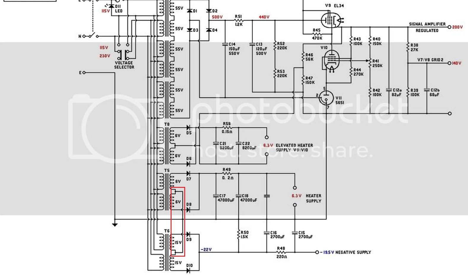
- Is there a reason why the GZ-34 rectifier is being replaced with solid-state diodes?
- Is there a reason why the EL-34 of the 670 is being used in place of the 6BL7 of the 660?
- There is an unlabeled cap near C18 in DaveP's schematic. What is the value and rating of that cap?
- I'm not seeing any wattage rating on these resistors but most of them I can infer when comparing to the original schematic. What's the rating for R51 (1.2k)?
- I see that T5 and T6 have their secondaries tied together, I assume to provide the -19.5V. If so, is there any consideration to polarity when doing this (i.e., inadvertently obtaining ~ +/-9V)?
- Is D11 an LED to indicate power? If so, wouldn't we want this powered from a lower voltage source (e.g., secondary of T8)? (Of course, with appropriate resistor.)
- Is R41 the "Zero" trimmer? This trimmer looks to be at the location of the trimmer for B+ on the 670, which has it's zero trimmer connected to -19V according to its schematic. There's no B+ trimmer on the 660 like there is on the 670 so I'm slightly confused here...
- I see R10 labeled as "PAD". Is this the threshold control?
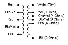
- I am slightly confused on the Hammond 1645 wiring. I assume the GR and BK connections as shown seemingly on the primary of the schematic are in reality the "4-ohm" secondary (obviously the WH and BK/Y are shown on the 70V secondary). But the remaining upper and lower coils on the schematic have the primary connected to the 6V6GT plates with the primary CT connected to B+ 440V. However, I can't determine the primary CT on the 1645 according to the Hammond's diagram as it seems there are multiple (?) primary CTs shown. Is the primary CT the red lead?
Chris
I may know the answer to some of the questions.
GZ34 would need 5V supply for the heater. Saves one transformer when solid state rectifier is used.
Triode connected EL34 is a low mu triode just like 6BL7.
Cap next to C18 voltage rating is more than 6.3V and capacitance doesn’t matter much since it’s parallel to a 47000u cap.
If I know my ohms law R51 seems to be dissipating 3W. I would say use a 10W resistor.
I don’t see T5 and T6 secondaries being tied together other than the center taps go to gnd. But we may be looking at different pictures.
D11 is probably a panel mount led pilot lamp for mains voltage.
Looks like meter zero was adjusted by adjusting the B+ voltage in the 660
That's what I was thinking. Thank you for confirming.GZ34 would need 5V supply for the heater. Saves one transformer when solid state rectifier is used.
This I did not know, something for me to research on!Triode connected EL34 is a low mu triode just like 6BL7.
Also what I inferred. Would it matter if I omitted it?Cap next to C18 voltage rating is more than 6.3V and capacitance doesn’t matter much since it’s parallel to a 47000u cap.
Ah, feel foolish for this. Thanks for the reminder!If I know my ohms law R51 seems to be dissipating 3W. I would say use a 10W resistor.
I am referring to the T5 and T6 designations not on the original but on DaveP's schematic (connected secondary CTs circled in red):I don’t see T5 and T6 secondaries being tied together other than the center taps go to gnd. But we may be looking at different pictures.
Got ya!D11 is probably a panel mount led pilot lamp for mains voltage.
OK, thank you for the confirmation.Looks like meter zero was adjusted by adjusting the B+ voltage in the 660
What do you think about my last point on what the CT is on the primary of the Hammond 1645?
Thank you!
Chris
What do you think about my last point on what the CT is on the primary of the Hammond 1645?
Red wire seems to be the primary CT
shabtek
Well-known member
they (secondaries) must be 'common' to 0volt/ground--notice the 'jumps' in the schematic where there is not a connection?
ps: thanks for bumpin' another awesome DaveP thread! and good luck
ps: thanks for bumpin' another awesome DaveP thread! and good luck
scott2000
Well-known member

looks like a connection there....?
D'oh! Rookie mistake!they (secondaries) must be 'common' to 0volt/ground--notice the 'jumps' in the schematic where there is not a connection?
 Thanks guys for setting me straight!
Thank you Guys for answering most of the questions for me!
The Hammond 1645 that I used was old stock, I believe that the secondary is wired differently now, check out before purchasing!
Any output transformer with the right ratio and power capacity will do the job. The critical factor is being able to get an output impedance of ~100 ohms, this gives the Fairchild the charging power and speed that it is famous for. I was pleased to hear that the owner of this compressor was able to sell it recently through Reverb for what he paid for it.
While I am here, I will be starting a new from scratch project later this year after two years of domestic upheaval! I have been asked to make a Fairchild 627 equaliser.
All the best
DaveP