[FEELER] C12 Clone Project

GroupDIY Audio Forum

Help Support GroupDIY Audio Forum:

This site may earn a commission from merchant affiliate links, including eBay, Amazon, and others.

Please indicate which project configuration would most interest you.

  • pcb's only

    Votes: 28 14.1%
  • pcb's and donor microphone

    Votes: 22 11.1%
  • partial kit (pcb, electronic components, transformer)

    Votes: 37 18.6%
  • partial kit with donor microphone

    Votes: 29 14.6%
  • complete turn-key package

    Votes: 83 41.7%

  • Total voters
    199
OK, now since this PCB  color business is volatile stuff that could easily set this place on fire, I've contacted a diplomat. Here's what he suggested. He said why not make the body sleeve a non-transparent metal. That way perhaps everybody can live with whatever the final outcome will be.
 
micaddict said:
OK, now since this PCB  color business is volatile stuff that could easily set this place on fire, I've contacted a diplomat. Here's what he suggested. He said why not make the body sleeve a non-transparent metal. That way perhaps everybody can live with whatever the final outcome will be.

That's an awfully rash solution.  ;)
 
Enchilada said:
tonycamp said:
Looks awesome fellas, I'm totally excited!, although i personally will not be partaking if the pcb is yellow! :mad:

;D

-1

A yellow PCB would be the business!

Hey now, easy there Enchilada,....No one said yellow's for sure yet! Sure  it would look flashy, but why would you want to compromise the integrity of the circuit and sound? :eek: ??? ::);D
 
We should put Matador in prototyping hell by requesting all colors to test for sonics.  We might have problems if the PSU sounds better in yellow with a blue mic pcb.

I've ordered some 4700pf and 1000pf K40Y PIO caps from the mother russia and have devised in my mind a way to make 'em fit nicely as they are significantly longer than the Justradios 630V styrenes we have in the prototype now.  I believe I will hack up a PCB to test.  I have a feeling I'm chasing my tail and the styrenes sound just great in comparison, but you never really know until you throw 'em circuit.

Trying to decide if I should air ship another HT-11A body $$$$$$ from China to speed up prototyping.
 
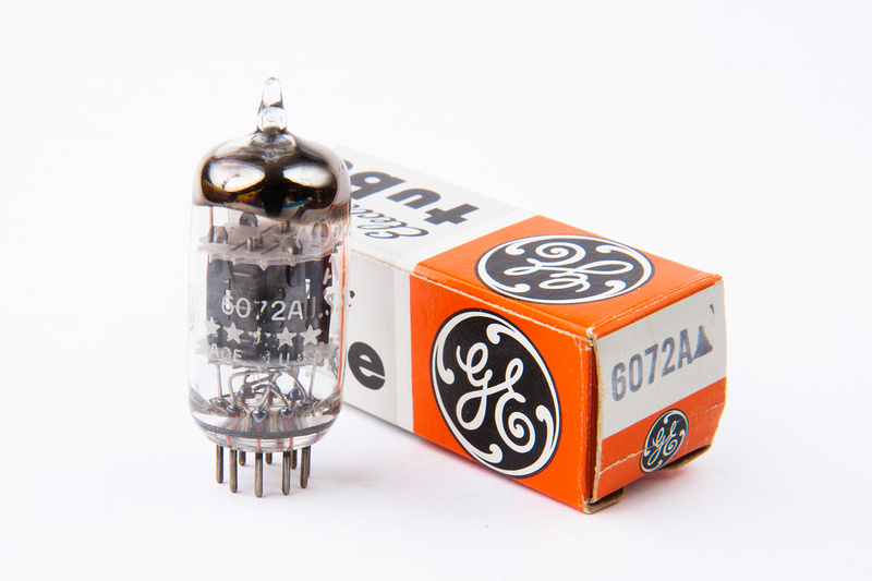
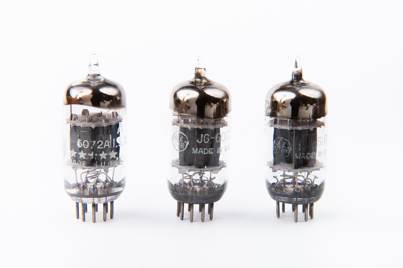
They exist still . . . in the wilds.  GE 6072a mic-grade tubes  ;D

p1286669790-4.jpg


p1286669878-4.jpg


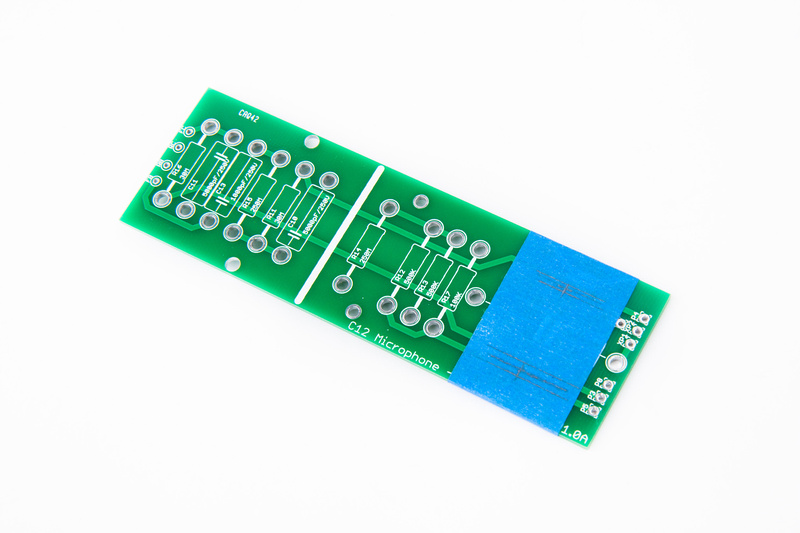
OK. . . I did say that I suck at prototyping because I lack diagnostic skills, but since we have the pcb's and I have some ideas in my head about component placement. . . here we go.  I'll just go ahead and bite off more than I can chew again.

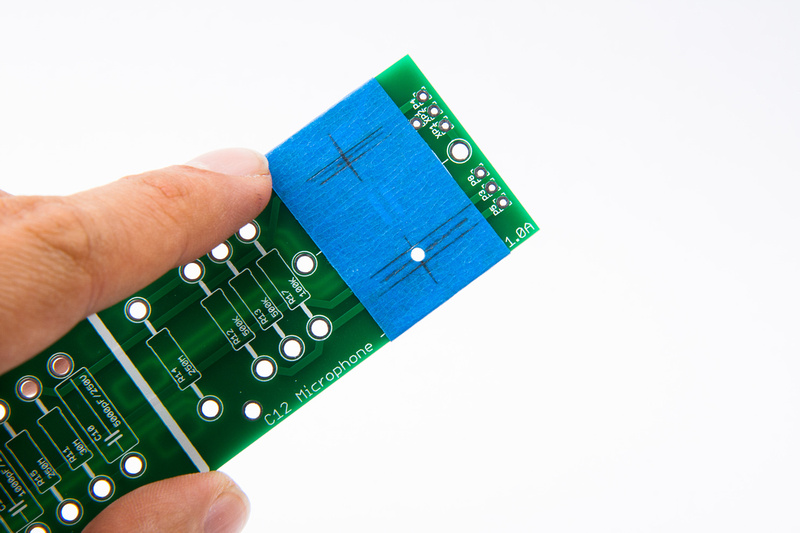
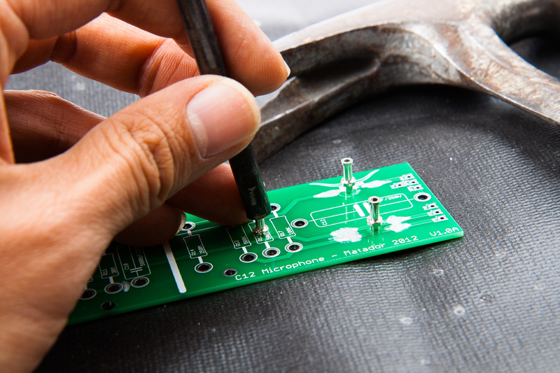
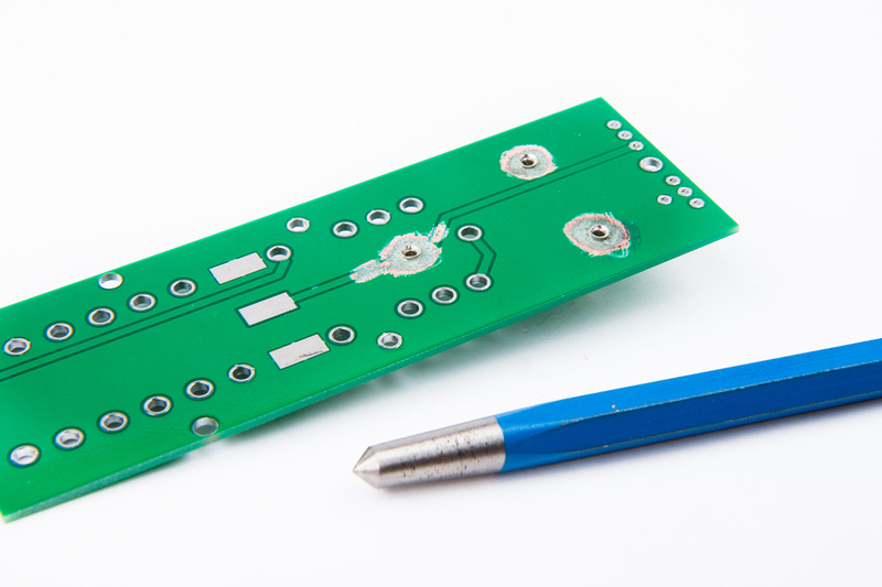
Marking the location of some new holes I need.

p1286669980-4.jpg


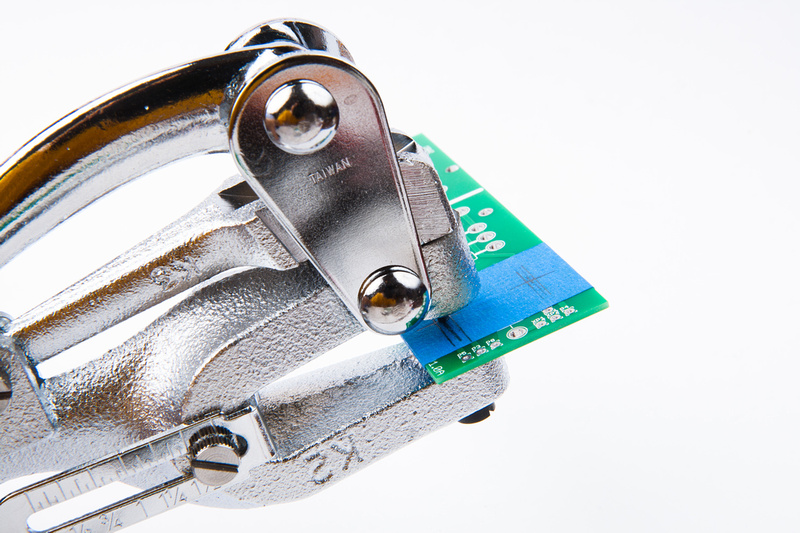
And, let's just get right to hacking up a perfectly good pcb.  This is a hole punch I bought to do my turret board version of ioaudio's mk47 psu.

p1286670092-4.jpg


Doesn't work half bad on a normal pcb.

p1286670336-4.jpg


Marking my location for my 3rd "extra" hole.

p1286670540-4.jpg


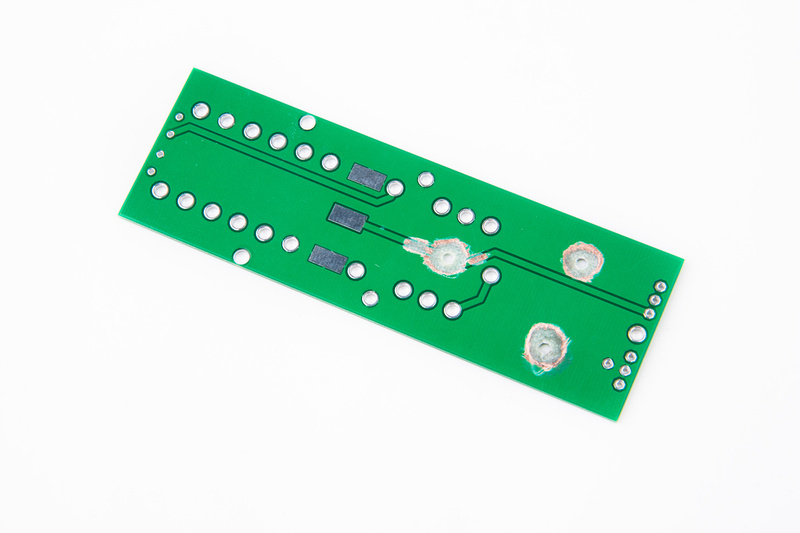
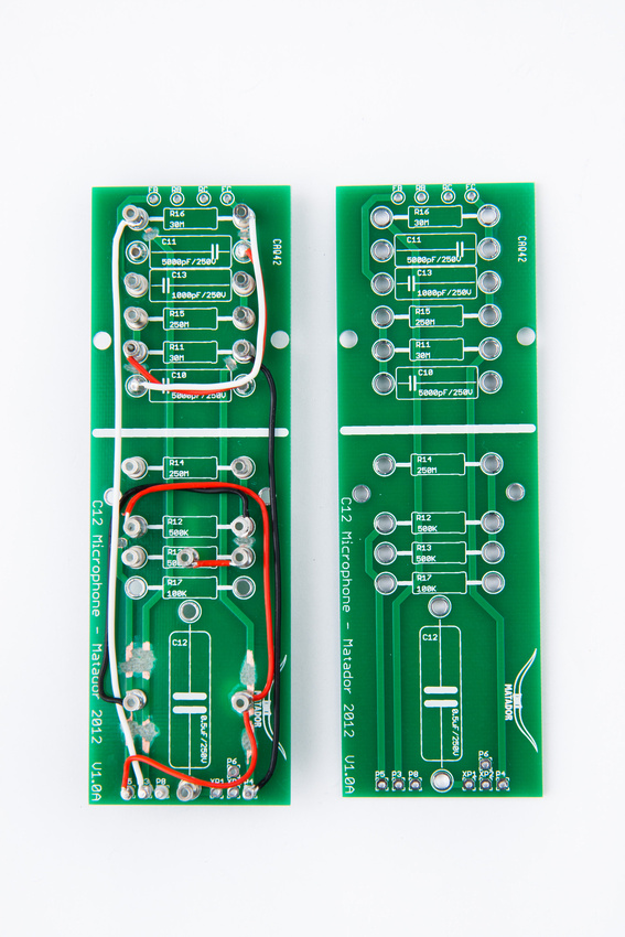
And new holes are in. . . What I'm trying to do is make a little more room length-wise for C12 by making R13 and R17 longitudinally oriented instead of perpendicular.

p1286670748-4.jpg


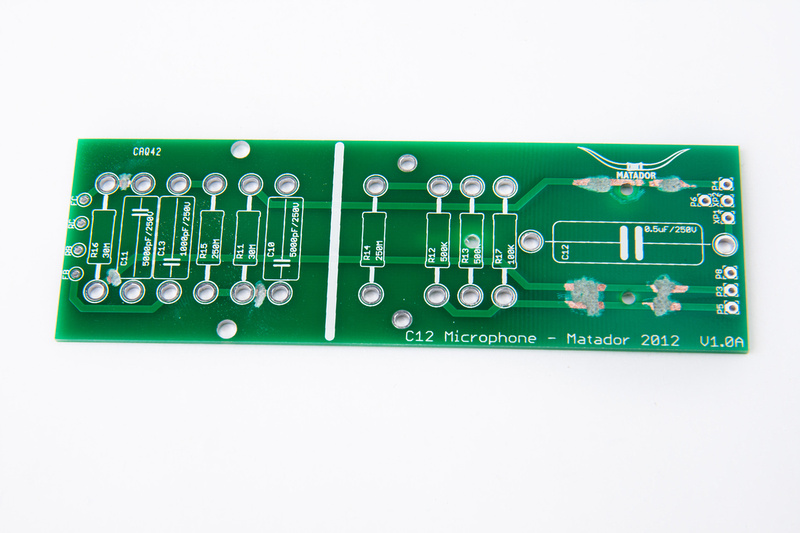
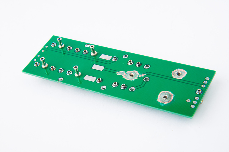
And some trace grinding.

p1286670874-4.jpg


And some more trace grinding and groundplane grinding on the back side.

p1286670992-4.jpg


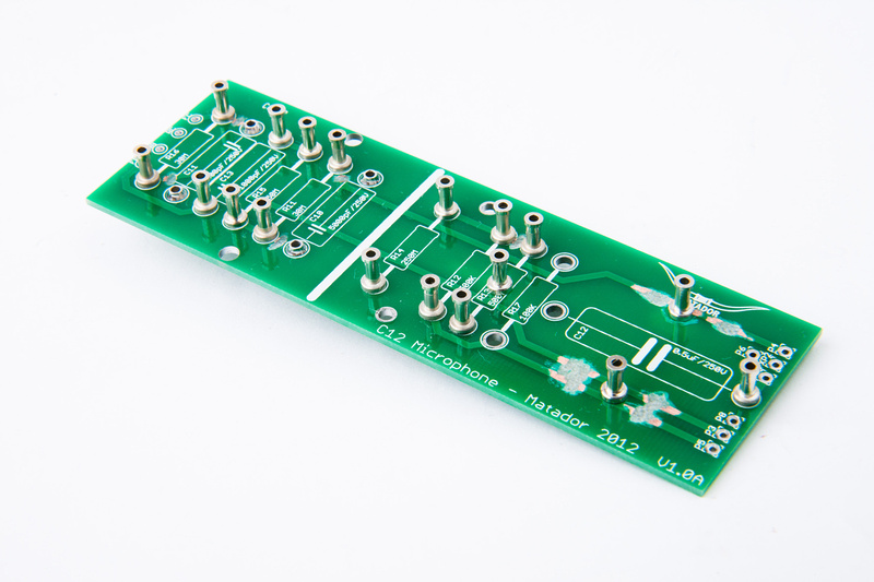
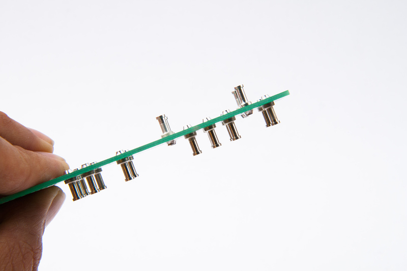
New turrets go in. . . the holes are optimized for press fitting so they work pretty well, but this pcb is much thinner than 1/8" G10 board.

p1286671090-4.jpg


So, I decide to swage the ends with a center punch because that's the only tool I had on hand.

p1286672106-4.jpg


Next, I solder in the turrets I will be utilizing on the pcb.

p1286672218-4.jpg


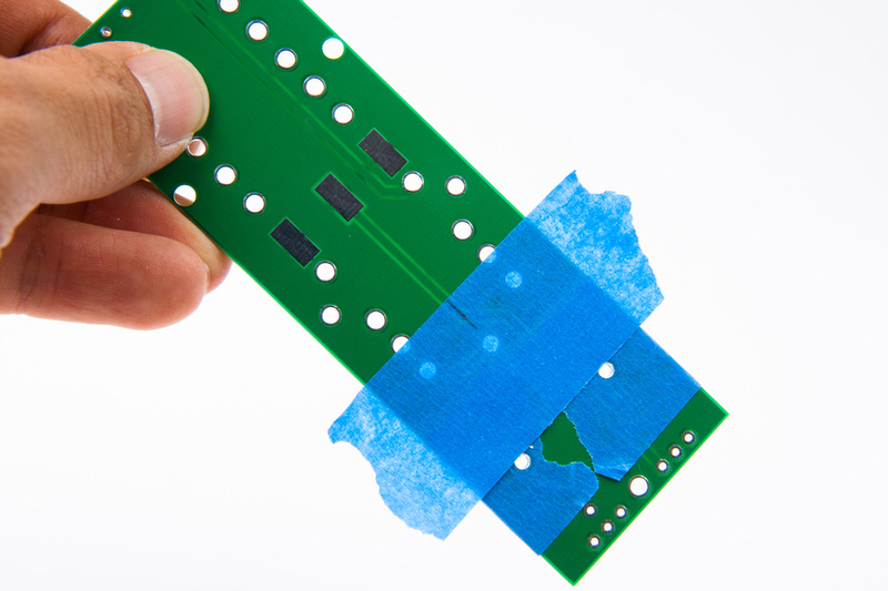
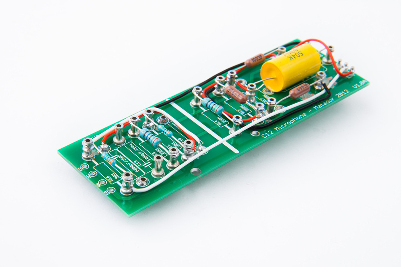
I'm also making a change on the top side of the mic in order to facilitate Russian PIO caps in the C10, C11, and C13 positions.  I'm moving C11 and C10 to the back side of the pcb and mounting them longitudinally to gain more length and width.  C13 will then have a bit more space because the space C11 used to occupy (right above it) has been vacated.

p1286672366-4.jpg


p1286672484-4.jpg


My suggestion to Matador was to leave out the traces on these C11 and C10 to give the option of building in either orientation.  A few leads will have to be manually configured, but  the build is very conducive to that.  But, knowing him, he'll come up with some awesome new configuration that would allow for both options natively.

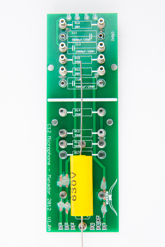
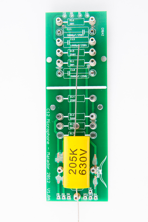
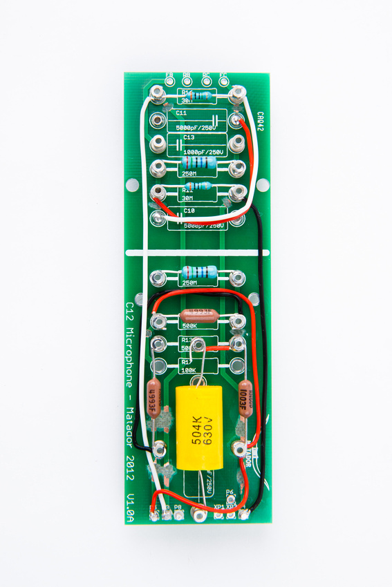
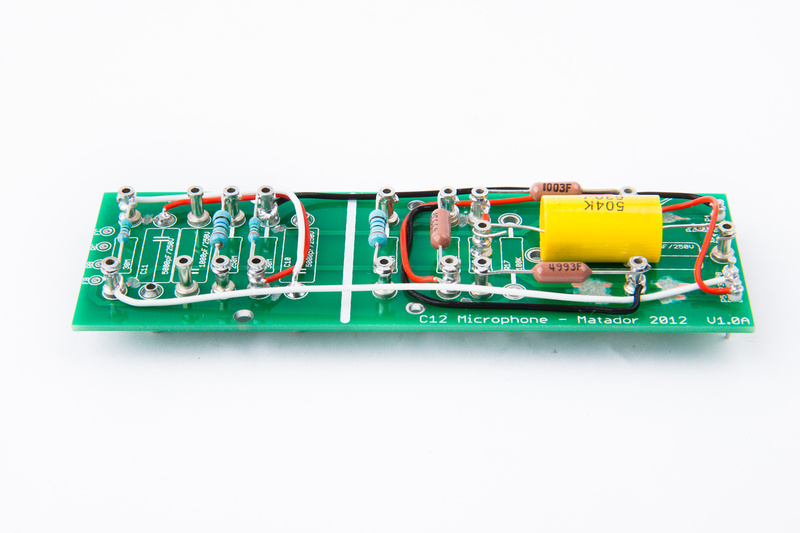
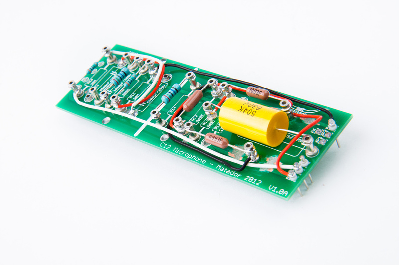
On the bottom side of the pcb, the main reason I'm trying to get a little more length on C12 is the 1uF capacitor that is commonly used in this microphone. . . this version was just barely too long for the v1.0 pcb and it really doesn't hurt to give some options on this cap.

p1286672542-5.jpg


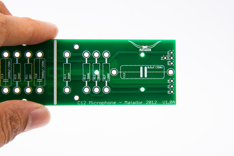
With my revised configuration, even moving up to 2uF 630V is ok.  R13 and R17 will ride along side.  You may also notice in the pic some more trace cutting has occurred.  I think I'm really setting myself up for failure here on this 2nd prototype  :eek:.

p1286672714-5.jpg


The look and function of the layout Matador came up with is pretty awesome. . . with everything lined up and spaced evenly perpendicular to the pcb.  I REALLY like it a lot and don't want to mess it up.  But the tube of the mic is just not wide enough to allow for the PIO's in that configuration.  Hopefully, this will be one way to retain the broad strokes of the nice look but open up a few more options.
 
Does the 2uF clear the shell, even if laying flat on the board?

If not, I may be able to make a lengthwise cutout in the center for C12 to gain a bit more room.
 
I've got to tell you guys this looks great. I'll have to get myself a pair of these kits to see if there's any possible optimization of the capsule.
 
;D

Hi, Tim. Good to see you. Some of us here didn't think you would chime in. I figured you would. And I didn't even have to notify or persuade you, behind the scenes.  :)

Anyway, the capsule is the heart and soul of a microphone. And we all know, for C12 style mikes, yours is the business. 

I've got to tell you guys this looks great. I'll have to get myself a pair of these kits to see if there's any possible optimization of the capsule.

Keep us posted, please.
 
Matador said:
Does the 2uF clear the shell, even if laying flat on the board?

If not, I may be able to make a lengthwise cutout in the center for C12 to gain a bit more room.

Hey Matador,

Using internal dimensions from my model (pic is posted in this thread), the 630V 1.5uF cap is .050" too big to fit.  The PCB is .060" thick so if you were to make a clearance cut under the capacitor location, it would fit.

At this point, however, there are many economical .5uF-3uF 250V and 400V capacitor options that would fit the C12 position without the cutout (Mundorf, Erse, Solen, etc.) .  630V is a bit overkill, no?

 
This is looking great! I particularly like the heavy duty turrets. Pretty awesome stuff. Will have to get in on a couple of these.

As for output caps I would vote for more room if at all possible just to maximize DIY options. Especially in that critical position.

In any case, this is well thought out with top of the line execution.

Cheers,
Jonathan
 
I am also looking forward to the final product! I'm not sure if Ill be able to afford one, but I tried a few mics and the C12 was my winner.. hopefully this makes things very affordable. great looking work! and a yellow PCB sounds cool!
 
OK, we're prototyping at the Chinese Labor Camp tonight.  . . It may look like I know what I'm doing but I assure you I do not.  I'd appreciate it if someone who actually knows what they are doing could look over my hacking with a fine toothed comb to confirm that I have routed everything re-routed properly.  2 caps and 2 resistors have been turned 90 degrees.  The rest of the jumpers are a result of new holes in the PCB landing right on top of traces.

p1289803558-5.jpg


p1289803870-5.jpg


Yee  hawwww!  It's a bit more ghetto than Matador's clean build, but if everything is routed correctly, it should be good enough to test the pio caps at C10, C11, and C13 from mother Russia and a few options and values for C12.

p1289804106-4.jpg


p1289804312-4.jpg


I drilled out the holes for cut traces that ran to the bottom wire lugs and pressed in some teflon isolated pins.  Should be solid.  My pcb hacking level is newbie.  This is actually the first time I ground traces.  Confidence inspiring I know.  :eek:

p1289826602-4.jpg
 
Hi Guys,

I thought i'd chime in with what ive got and what i think my Apex 460 sounds like.

Apex 460
RK-12 capsule
Sowter 9610 transformer
mullard 12AT7 valve

I have changed a few of the resistors and caps, i will have a look for which ones, but im pretty sure its the obvious ones that everyone changes.
My Apex 460 sounds amazing on vocals and acoustic guitar, really happy with the sound.
thinking about building a new one using the Matador pcb etc.
great info and build top marks to everyone for their continuing support.

regards

SPence.
 

Latest posts

Back
Top