


What is 12 x 12 grilling, if you can explain it to me I can measure my head basket for you to check ?
You are using an out of date browser. It may not display this or other websites correctly.
You should upgrade or use an alternative browser.
You should upgrade or use an alternative browser.
[FEELER] C12 Clone Project
- Thread starter chunger
- Start date
Help Support GroupDIY Audio Forum:
This site may earn a commission from merchant affiliate
links, including eBay, Amazon, and others.
These guys say it better than I could
http://www.wirecloth.com/cwc/howto.htm
http://www.wirecloth.com/cwc/howto.htm
On my headbasket there are 12 wires per inch & the wire diameter is 0.64mm
The band over the top of the basket is 5mm in width, The height of the headbasket including the band at the bottom is approximately 66mm high.
The band over the top of the basket is 5mm in width, The height of the headbasket including the band at the bottom is approximately 66mm high.
chunger
Well-known member
Thanks for that critical data. It appears my Eyeball Mark 1 is functioning pretty well because the original HT-11A headbasket is about 66mm tall. The c12 body is 3.4mm wider than c12, and I increased headbasket height by 4mm to match proportions  . Based on squinting at internet pics. The human eye is an ingenious device.
. Based on squinting at internet pics. The human eye is an ingenious device.chunger
Well-known member
Rob Flinn said:Hi chunger.
I'm looking at your assembled mic pcb's & am wondering if the whole assembly would fit inside a 38mm inside diameter tube ? From your previous posting I can see that the width of the board is about 38 mm. but with the semi circular board attached it looks like the whole assembly needs a wider tube than the 38mm that the original is. COuld you confimr either way ? The reason being that your boards could be a neat solution for my build using original metalwork, but I suspect it may be a bit too big.
Hi Rob,
I don't think this will fit in a 38mm tube. . . Here are some of the development drawings from measurements I took from the microphone for Matador to design the PCB. Sorry, we designed it pretty tight to the HT-11A donor body due to space constraints in the tube.
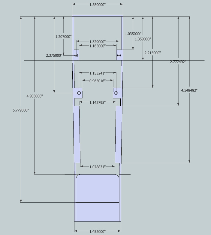
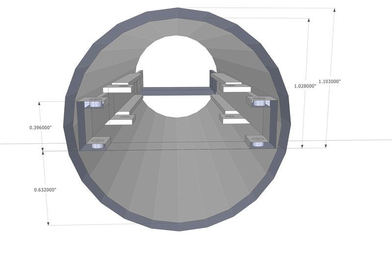
Guess this would be of help to others who may want to develop on this donor body as well.
Melodeath00
Well-known member
- Joined
- Jun 7, 2012
- Messages
- 416
micaddict said:I'm already on Tim's list for a "standard" CT12. What to do now? :-\
OK, seriously now. I believe Tim himself (but I can't speak for him) prefers the full air and detail of the original, although those likely varied, too. From what I recall (but again, don't take my word for it) Jim Jacobsen asks Tim to "tame" the capsules a little in the highs, for his (C12 inspired) Dutch microphone.
Still, such (a) large membrane(s) without the center screw will always sound somewhat scooped, albeit in a broad an smooth way.
You could try to compensate right at the beginning i.e. at the capsule, but there's only so much you can do there. Also, I'm not sure if that's a wise thing to do. More about this later.
Micaddict, could you expand on this? I haven't seen anyone say Tim Campbell's capsule for this project would be different from his standard CT12. Did I miss something?
Also curious how Oliver's T14 variants differ sound-wise from his regular T14?
Chunger, I think it would be ridiculously cool if somehow there were a way to get a similar capsule mount to the original C12. It partically obscures the rear of the diaphragm, whch has an effect on the mic's sound as well, naturally. It looks something like this
http://www.telefunken-elektroakustik.com/images/mics/photo_galleries/C12-06.jpg


![Electronics Soldering Iron Kit, [Upgraded] Soldering Iron 110V 90W LCD Digital Portable Soldering Kit 180-480℃(356-896℉), Welding Tool with ON/OFF Switch, Auto-sleep, Thermostatic Design](https://m.media-amazon.com/images/I/41gRDnlyfJS._SL500_.jpg)


micaddict
Well-known member
Micaddict, could you expand on this? I haven't seen anyone say Tim Campbell's capsule for this project would be different from his standard CT12. Did I miss something?
I only meant to say there could be a choice there (like there seems to be with the T14).
It had been a while since I read Jim Jacobsen's comments on the Campbell capsules he uses for the Dutch. Hence my disclaimer in the same post.
I did a little search and found one of the relevant Gearslutz threads form 2010. If need be, I might be able to find more.
Anyway, here's a quote:
And here's the thread:The recent batch of capsules that Tim sent me has a little more bass and is slightly warmer then some of his other capsules. The capsules he sent were a copy of a particular CK12 capsule that was warmer. I like the way that he can tune the capsules for different applications.
http://www.gearslutz.com/board/gear-shoot-outs-sound-file-comparisons-audio-tests/537741-apex-460-vs-dutch.html
As for the T14, I didn't know about the different voicings until this thread was started. As a matter of fact, I was going to order a T14, along with the T67 I'll be needing for the DU67 build, but I'm waiting for news now, too.
chunger
Well-known member
We won't know anything until we test and get ears on everything. . .
So far, I have not heard back from Oliver regarding my request to purchase test samples so the initial prototype configuration will likely be with the Cinemag 2480 that we we have on hand, so that is where we will start paired with the stock CT12 capsule.
Capsules and transformers are all sensitive to the smallest of spec changes. People who have good intuition, experience, and data of course can tweak those specs for a customer especially if they are very specific about the desired changes. As of right now, we have no concrete plans options other than the stock offerings. I wouldn't want to deter anyone from going ahead with planned purchases on account of this little experiment here. If all goes well with the stock options, I'm inclined to keep them that way and assume that Tim and Oliver both have made significant efforts to keep their products as close as possible to the middle-of-the-road original configurations.
I am moving forward with custom headbasket prototyping as fast as possible now that I have gathered the dimensional specs I need. Hopefully the factory I'm now dealing with can be nimble and get that ready quickly. Shipping for small, light packages from China is pretty fast, so I am optimistic.
micaddict
Well-known member
If all goes well with the stock options, I'm inclined to keep them that way and assume that Tim and Oliver both have made significant efforts to keep their products as close as possible to the middle-of-the-road original configurations.
Yes, that seems to be a wise thing to do, in any case at this point.
And hey, it's your (and Matador's) show.
BTW, I only started my ravings as a reaction on what you said in reply #30:
I was also lucky that AES is in town this weekend, so I had a chance to speak with Oliver Archut from Tab Funkenwerk at length regarding T-14 transformers and he is amicable to sourcing these to me for this project. He suggested 3 variants of his T-14 for me to try and gave some insight into optimizing to Tim Campbell's CT12 capsule.
Oliver knows this capsule well and recommends a custom winding on the T-14 to optimize for the bass and treble footprint of Tim's CT12.
Melodeath00
Well-known member
- Joined
- Jun 7, 2012
- Messages
- 416
Ah yes, I remember the post. I've read probably every JJ Audio post on the forum haha. But actually, while I know Jim Jacobsen said he was going to get Tim to tune the capsule specifically to the Dutch, I didn't take that particular post you quoted to describe the tuning for the Dutch. I thought Jim was simply saying that Tim's capsules vary in tone and the ones he was referring to happened to be warmer, but not that he uses a darker capsule in his Dutch now. I would probably request a "standard" (middle of the road?) CT12 if I was in the market right now. I know Blackspade also has the CT12 tuned to sound more like a 251 in the UM25C. It's very cool to have options.micaddict said:Micaddict, could you expand on this? I haven't seen anyone say Tim Campbell's capsule for this project would be different from his standard CT12. Did I miss something?
I only meant to say there could be a choice there (like there seems to be with the T14).
It had been a while since I read Jim Jacobsen's comments on the Campbell capsules he uses for the Dutch. Hence my disclaimer in the same post.
I did a little search and found one of the relevant Gearslutz threads form 2010. If need be, I might be able to find more.
Anyway, here's a quote:
And here's the thread:The recent batch of capsules that Tim sent me has a little more bass and is slightly warmer then some of his other capsules. The capsules he sent were a copy of a particular CK12 capsule that was warmer. I like the way that he can tune the capsules for different applications.
http://www.gearslutz.com/board/gear-shoot-outs-sound-file-comparisons-audio-tests/537741-apex-460-vs-dutch.html
I find it interesting that there are many variations of the T14. I thought it was built to historical spec, and Tim's capsule is also built to historic spec, so it's kind of funny the transformer can be "tuned" to this specific capsule. Of course, I'm not an electronics expert.
For what it's worth, I was told that AMI's C12 kit should be available in early 2013, but I could see it being delayed again. It might be hard to work in such a thin body, but again, I am no expert. Never built a mic.
Chunger, any opinions on doing a "clamping" capsule mount like the original C12?
chunger
Well-known member
I really won't know until I get ears on. I'm assuming transformers are kindof like pickups in that there are many variables that effect tone that can all be controlled. . . also, it is the sort of thing that specialized knowledge is required to do correctly. I my bass guitar adventures, I was unable to find a suitable budget oversea's manufactured one and ended up with a top-tier premium brand state-side and even then, I ended up not liking the stock leanings and had custom coil shape and winding made for my application after iterative testing. Opinions on this sort of thing are subjective but again. . . won't know until I get ears on it.
Oliver did have something in mind specific to Tim's Capsule so I would like to at least hear it unless he is too busy to do a custom right now.
Oliver did have something in mind specific to Tim's Capsule so I would like to at least hear it unless he is too busy to do a custom right now.
micaddict said:If all goes well with the stock options, I'm inclined to keep them that way and assume that Tim and Oliver both have made significant efforts to keep their products as close as possible to the middle-of-the-road original configurations.
Yes, that seems to be a wise thing to do, in any case at this point.
And hey, it's your (and Matador's) show.
BTW, I only started my ravings as a reaction on what you said in reply #30:
I was also lucky that AES is in town this weekend, so I had a chance to speak with Oliver Archut from Tab Funkenwerk at length regarding T-14 transformers and he is amicable to sourcing these to me for this project. He suggested 3 variants of his T-14 for me to try and gave some insight into optimizing to Tim Campbell's CT12 capsule.
Oliver knows this capsule well and recommends a custom winding on the T-14 to optimize for the bass and treble footprint of Tim's CT12.
desol
Well-known member
- Joined
- Jun 20, 2005
- Messages
- 2,176
Melodeath00 said:...so it's kind of funny the transformer can be "tuned" to this specific capsule.
That's how you get amazing sounding microphones. Parts tuned and matched in configurations based on experience and listening. You can't just throw stuff together (even quality stuff) based on specs, and expect something that sounds amazing.
Matador
Well-known member
Some more on the PSU build.
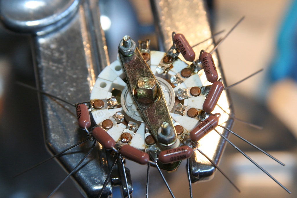
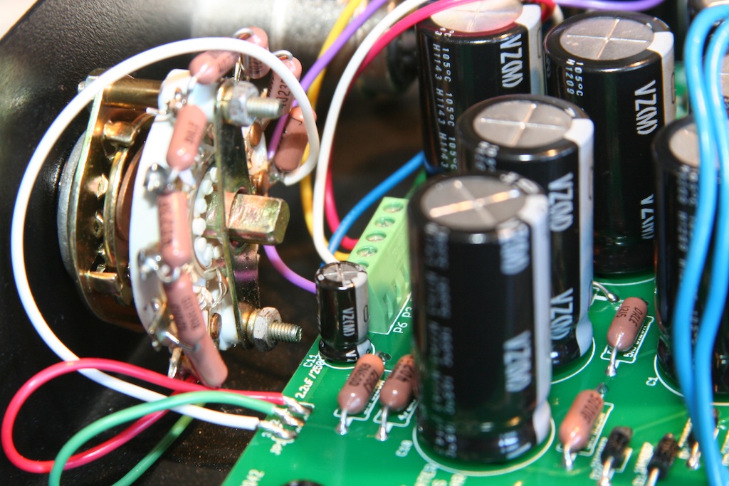
So the stock Alctron unit has an 8-position switch for the polarization supply. It comes stuffed with 150K resistors. The original C12 used 400K resistors, so these have to go. I left the switch in so that it wouldn't move for this step.
NOTE: the knob is a PITA to get off. It has a plastic lid that snaps off, and there is a captive nut that must be loosened. I didn't realize this, and I destroyed it to get it off. Now you don't have to sacrifice the one on your unit should you wish to remove it.
So a touch of solder on each resistor junction loosens them up enough to lift out:
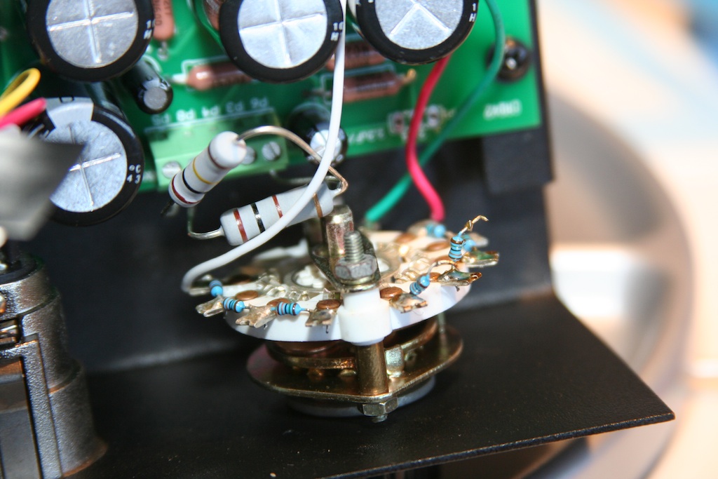
Once they are all out I removed the entire switch from the case so I could have easier access to everything:
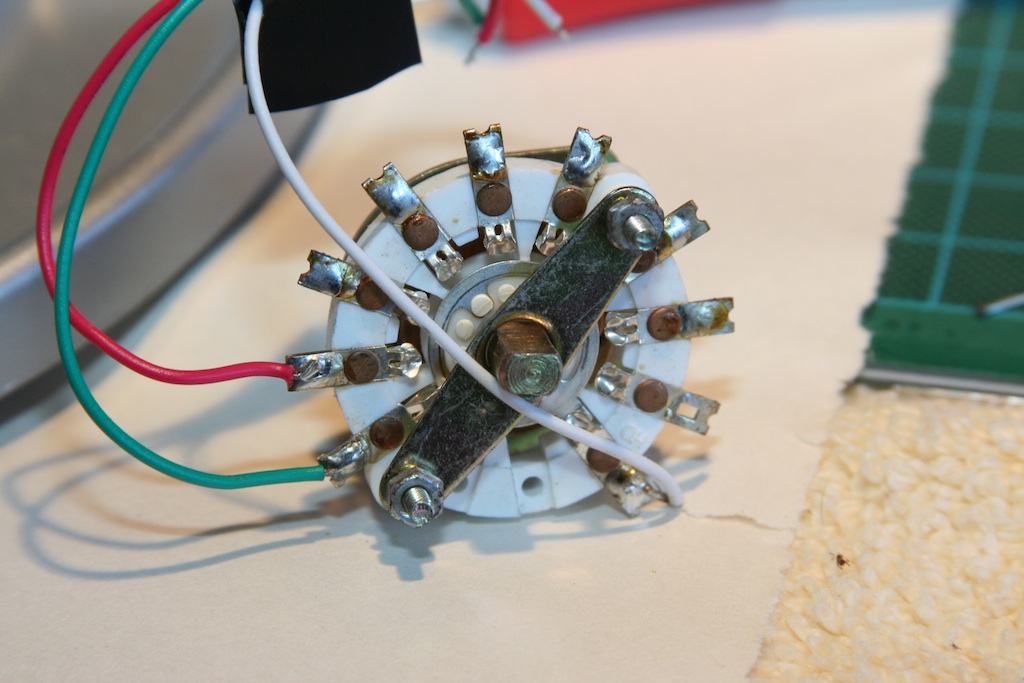
So you can see this is essentially equivalent to a stepped pot, with wire leads at each end (the red and white wires) and one at the "wiper" (green) that moves between each resistor.
First use some solder braid to suck out the extra solder and expose the holes in the lugs for the new resistor leads. DO THIS QUICKLY: the switch isn't the highest quality, and the lug carrier is plastic, and it will begin to deform and move should you leave the iron on for too long.
Are stuffing and soldering the new 400K resistors, we are here:
Clip of the extra resistor leads, then I attach three new wires of the same colors:
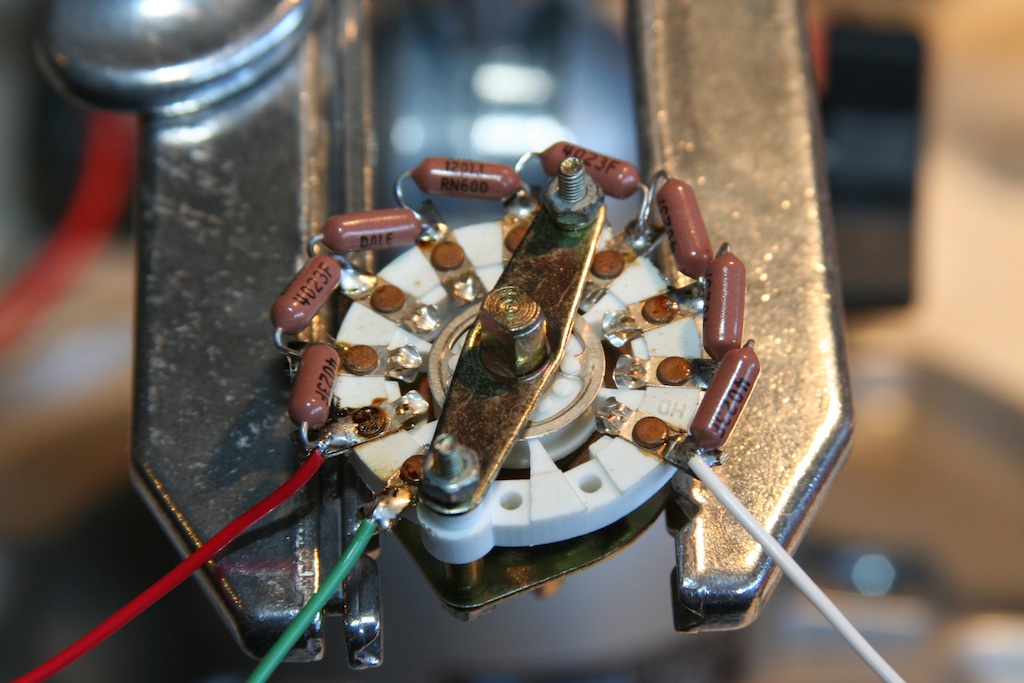
Test the switch out: you should read 8x400K or 3.2M between the "outer" wires (the red and white). If you declare the white wire ground, then you should read between 0 ohms and 3.2M between the white and green wires in 8 steps of 400K. Make sure this is all working before you put the switch back in.
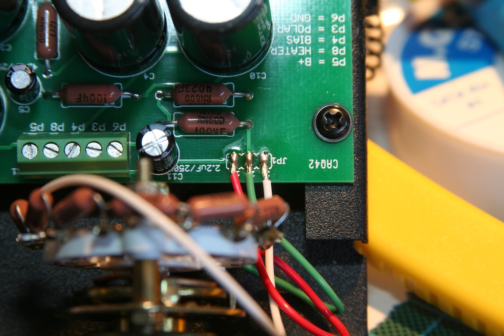
The board layout from left to right is:
1 - B+
2 - Polarization out
3 - Ground
So to match up the front panel painting to the circuit: in order to get omni, we need the green and red shorted together. This means the following mapping will make the front panel correct:
1 - red
2 - green
3 - white
Here is this wired up:
Now on to the XLR plugs.
For some reason, whoever decided to build these used the unused pin 4 as a solder joint to tie the supply to ground. This won't do, as we need pin 4 to be our new bias wire. So I removed the white wire from pin 4, then bent it back straight so I could attach a new white wire. Pin 7 is also ground, and you'll see a small resistor lead soldered between pin 7 and the XLR socket housing tab. So after the new white wire is attached to pin 4, a piece of heat shrink makes it isolated like all the rest:
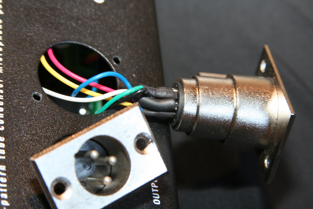
Now that there is no white wire carrying ground, we must add one. I chose purple. I soldered it directly to the ground tab at the top of the 7 pin XLR jack. This goes back to the screw terminal.
So I decided to follow the Alctron pin assignments and not the C12 one. I figured there was a higher chance people would want a stock Apex 460 or ELM M251 copy to work with this PSU, and since pin 4 isn't used in the Apex or Alctron there is no incompatibility.
As a result, here are the assignments:
Pin 1 - 120V B+
Pin 2 - 6.3V heater supply
Pin 3 - Polarization voltage
Pin 4 - Negative Bias Supply
Pin 5 - Audio -
Pin 6 - Audio +
Pin 7 - Ground
And here is that all wired up:
If you don't like the stepped switch, a Lorlin or Grayhill could be used. Or, even a 1M pot would work, provided there was a center detent so that the cardioid mode would really be cardioid consistently (the polarization must be half the supply to get this pattern).
Some initial mike pics next.
So the stock Alctron unit has an 8-position switch for the polarization supply. It comes stuffed with 150K resistors. The original C12 used 400K resistors, so these have to go. I left the switch in so that it wouldn't move for this step.
NOTE: the knob is a PITA to get off. It has a plastic lid that snaps off, and there is a captive nut that must be loosened. I didn't realize this, and I destroyed it to get it off. Now you don't have to sacrifice the one on your unit should you wish to remove it.
So a touch of solder on each resistor junction loosens them up enough to lift out:
Once they are all out I removed the entire switch from the case so I could have easier access to everything:
So you can see this is essentially equivalent to a stepped pot, with wire leads at each end (the red and white wires) and one at the "wiper" (green) that moves between each resistor.
First use some solder braid to suck out the extra solder and expose the holes in the lugs for the new resistor leads. DO THIS QUICKLY: the switch isn't the highest quality, and the lug carrier is plastic, and it will begin to deform and move should you leave the iron on for too long.
Are stuffing and soldering the new 400K resistors, we are here:
Clip of the extra resistor leads, then I attach three new wires of the same colors:
Test the switch out: you should read 8x400K or 3.2M between the "outer" wires (the red and white). If you declare the white wire ground, then you should read between 0 ohms and 3.2M between the white and green wires in 8 steps of 400K. Make sure this is all working before you put the switch back in.
The board layout from left to right is:
1 - B+
2 - Polarization out
3 - Ground
So to match up the front panel painting to the circuit: in order to get omni, we need the green and red shorted together. This means the following mapping will make the front panel correct:
1 - red
2 - green
3 - white
Here is this wired up:
Now on to the XLR plugs.
For some reason, whoever decided to build these used the unused pin 4 as a solder joint to tie the supply to ground. This won't do, as we need pin 4 to be our new bias wire. So I removed the white wire from pin 4, then bent it back straight so I could attach a new white wire. Pin 7 is also ground, and you'll see a small resistor lead soldered between pin 7 and the XLR socket housing tab. So after the new white wire is attached to pin 4, a piece of heat shrink makes it isolated like all the rest:
Now that there is no white wire carrying ground, we must add one. I chose purple. I soldered it directly to the ground tab at the top of the 7 pin XLR jack. This goes back to the screw terminal.
So I decided to follow the Alctron pin assignments and not the C12 one. I figured there was a higher chance people would want a stock Apex 460 or ELM M251 copy to work with this PSU, and since pin 4 isn't used in the Apex or Alctron there is no incompatibility.
As a result, here are the assignments:
Pin 1 - 120V B+
Pin 2 - 6.3V heater supply
Pin 3 - Polarization voltage
Pin 4 - Negative Bias Supply
Pin 5 - Audio -
Pin 6 - Audio +
Pin 7 - Ground
And here is that all wired up:
If you don't like the stepped switch, a Lorlin or Grayhill could be used. Or, even a 1M pot would work, provided there was a center detent so that the cardioid mode would really be cardioid consistently (the polarization must be half the supply to get this pattern).
Some initial mike pics next.
Matador
Well-known member
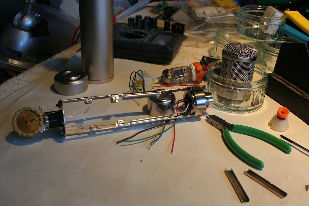
MORE PITCHERS! Here is a teardown of the stock Alctron mike.
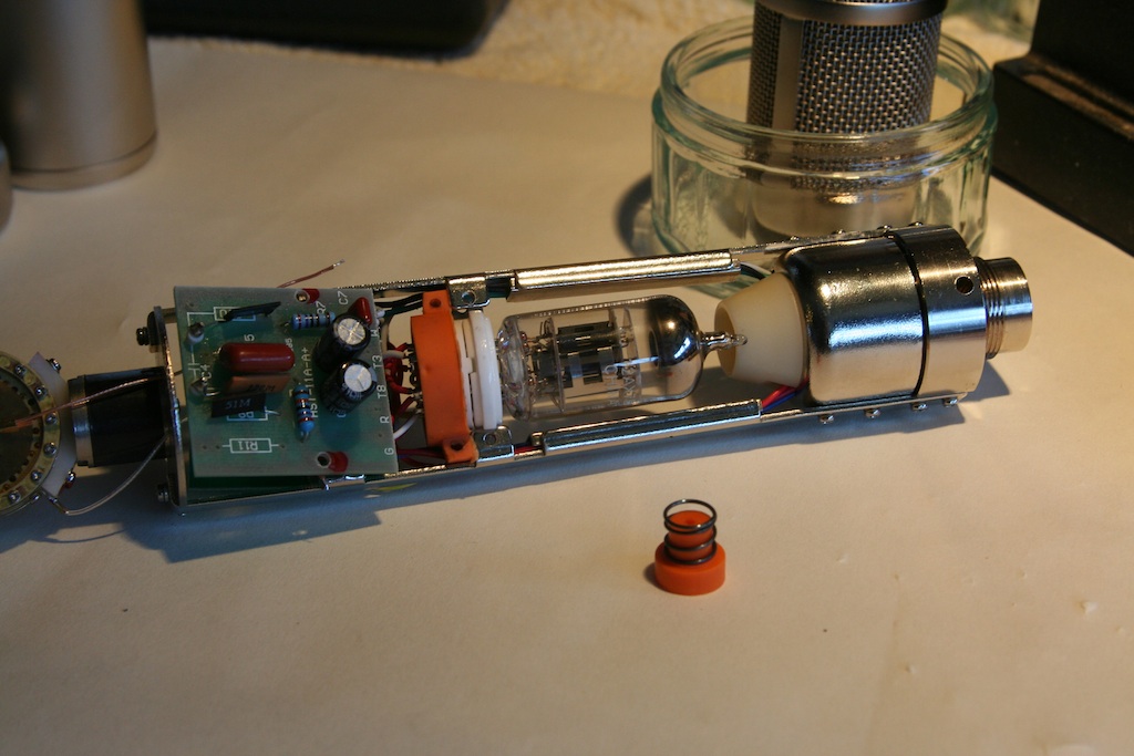
Here is the sample in all of it's naked glory:
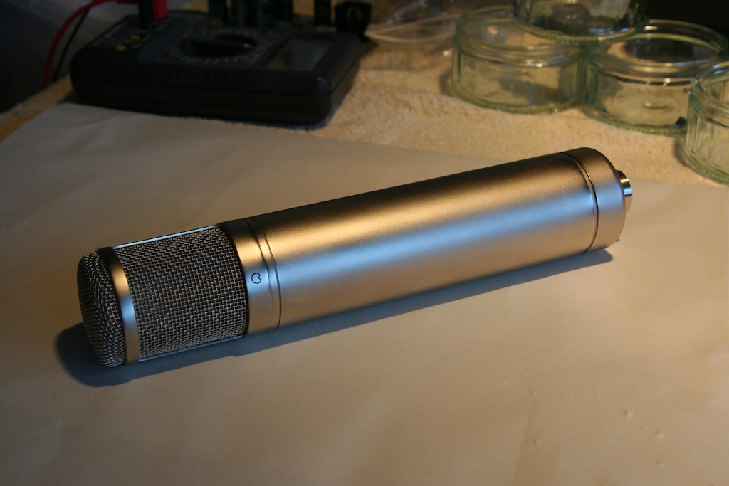
A few short spins of the retaining ring and off comes the body to reveal all of the guts.
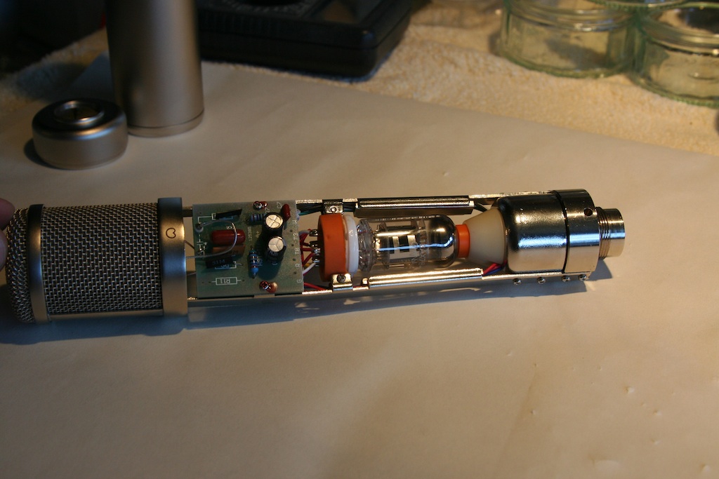
The head basket is removed with two small screws:
4 more screws release the two small PCB's:
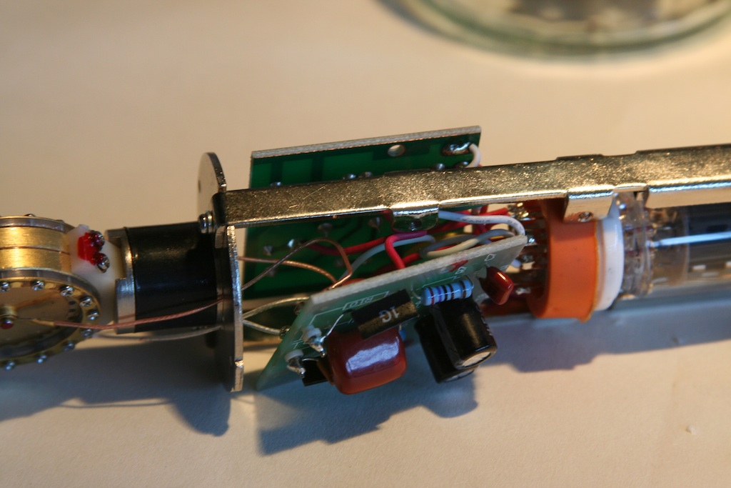
Two longer screws to remove the rubber tube socket retaining mount from the frame. This allows the tube tensioning spring to come loose and be taken out:
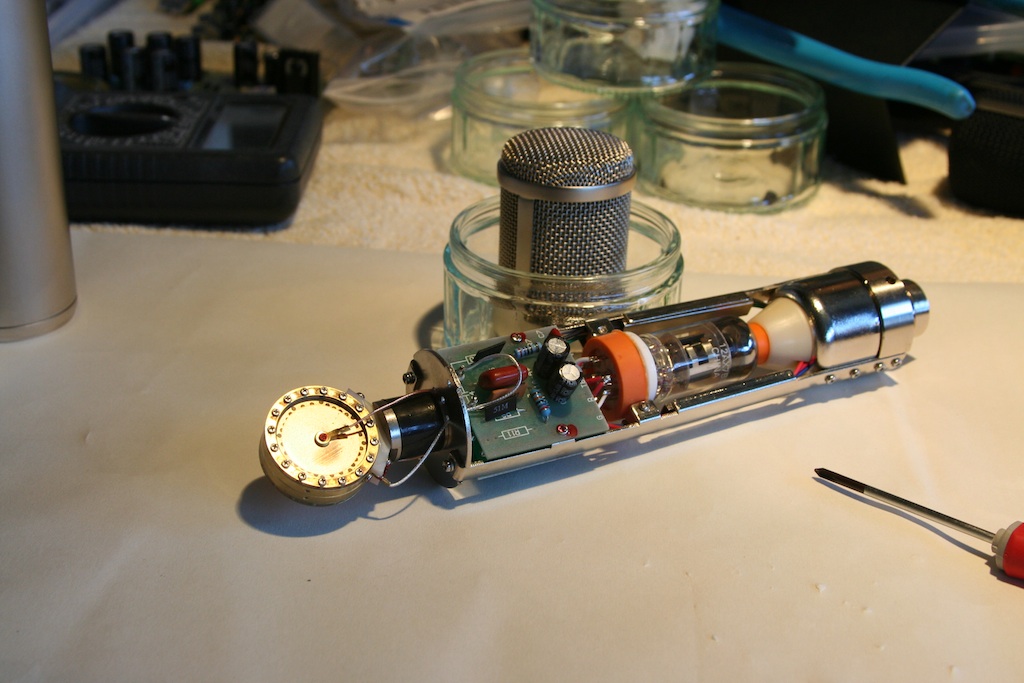
The wire cutters are used on the 7 wires coming up from the bottom of the mike, right where they attach to the PCB's and tube socket. After desoldering the capsule leads, all of the electronics lift out of the frame:
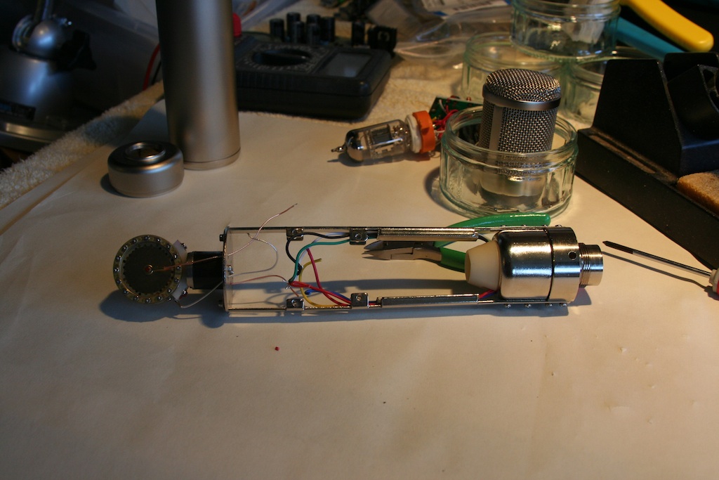
There are two metal wire-retaining brackets: one on each side. These hold the wires tight in a routing channel that is formed between these brackets and the side frame. They just pry loose with a screwdriver:
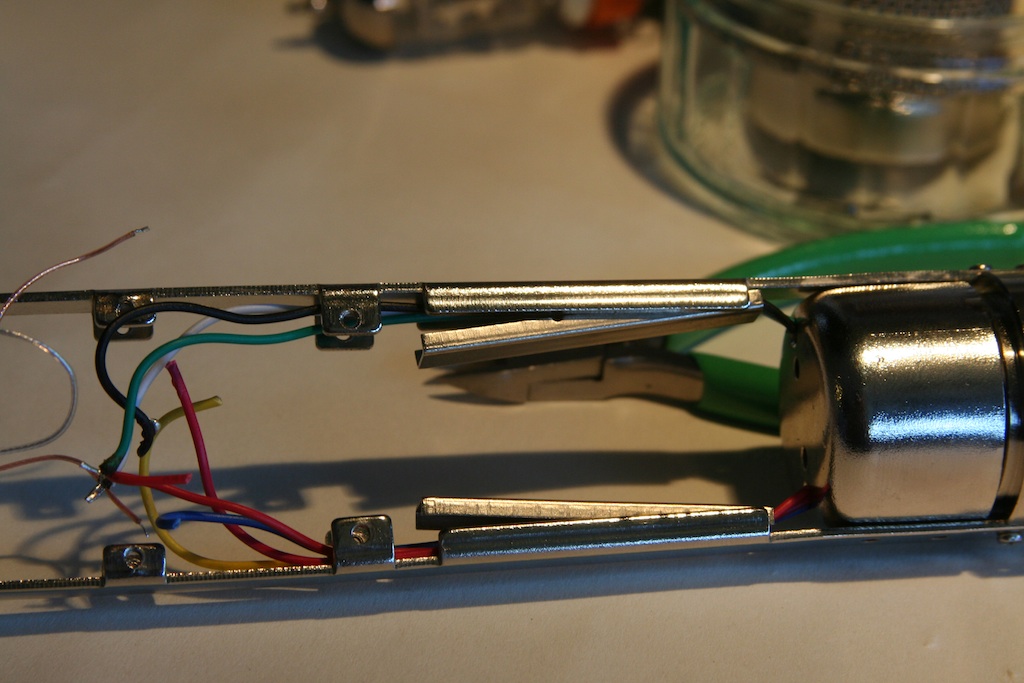
Then 4 more screws to remove the transformer housing. It just slides right up the wire bundles, and reveals the stock transformer:
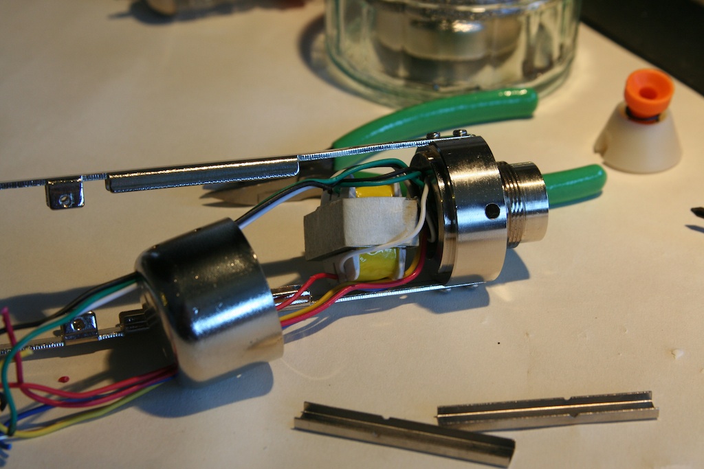
Once the transformer housing is removed, the mike is stripped naked and is ready for new guts!
A few notes: for some reason, pretty much ALL of the small screws were stripped out. It was not this way on my Apex 460, so I don't know if this was just something they send as B-stock prototypes or what. In any case, I see my 2-56 tap and drill set is going to get a bit of a workout!
All in all, not a big deal: there's only 6 screws or so. But I like to know that everything is at least held together well before I start adding new parts.
Here is the sample in all of it's naked glory:
A few short spins of the retaining ring and off comes the body to reveal all of the guts.
The head basket is removed with two small screws:
4 more screws release the two small PCB's:
Two longer screws to remove the rubber tube socket retaining mount from the frame. This allows the tube tensioning spring to come loose and be taken out:
The wire cutters are used on the 7 wires coming up from the bottom of the mike, right where they attach to the PCB's and tube socket. After desoldering the capsule leads, all of the electronics lift out of the frame:
There are two metal wire-retaining brackets: one on each side. These hold the wires tight in a routing channel that is formed between these brackets and the side frame. They just pry loose with a screwdriver:
Then 4 more screws to remove the transformer housing. It just slides right up the wire bundles, and reveals the stock transformer:
Once the transformer housing is removed, the mike is stripped naked and is ready for new guts!
A few notes: for some reason, pretty much ALL of the small screws were stripped out. It was not this way on my Apex 460, so I don't know if this was just something they send as B-stock prototypes or what. In any case, I see my 2-56 tap and drill set is going to get a bit of a workout!
All in all, not a big deal: there's only 6 screws or so. But I like to know that everything is at least held together well before I start adding new parts.
Matador
Well-known member
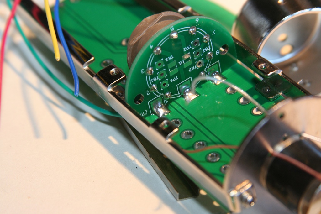
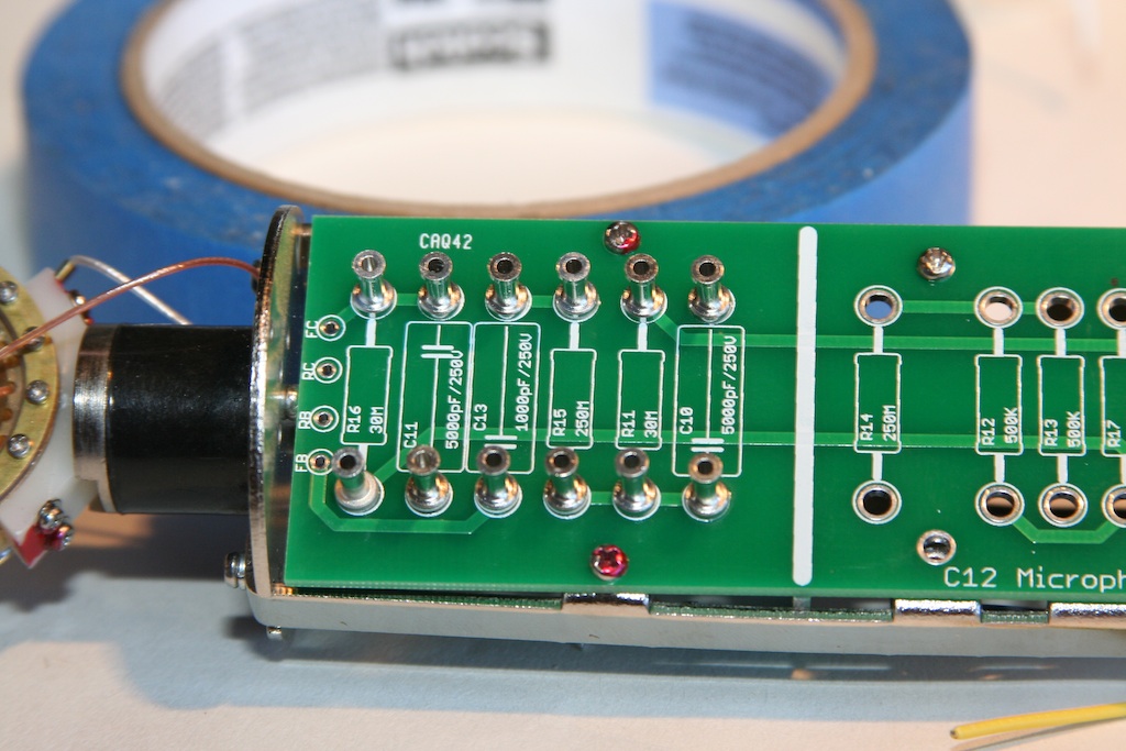
So here's the part of the build I've been dreading: fitting the PCB to the frame. This is the most hazardous part of the project because if I messed up my screw holes, the first prototype will be taped together on the inside...which is never confidence inspiring.
However as usual, Chunger's detailed drawings left nothing up to interpretation and all 4 mounting holes lined up exactly!
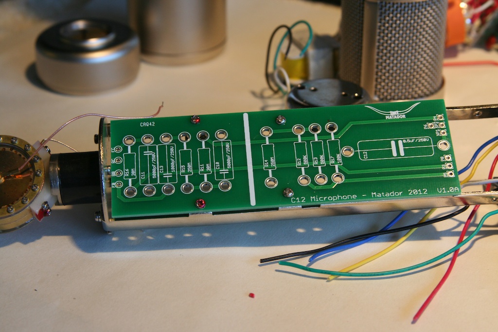
There is a good 1/4" gap between the bottom of the PCB and the top of the transformer housing, so no clearance issues there.
The next bit of nervousness: I had to draw the layout for the PCB tube socket based on a sketchy drawing. I made a few assumptions based on other sockets I had, and expanded the holes slightly so I had a bit of slop. But no problems here either: the PCB socket lined up perfectly.
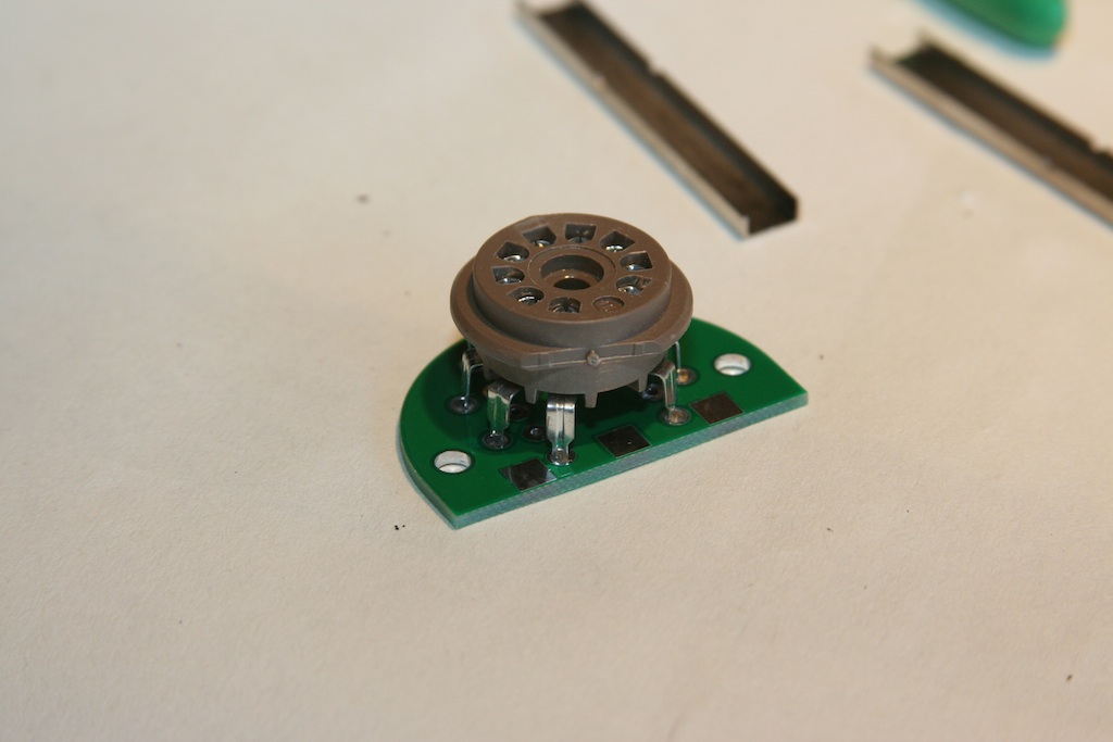
So I flip this over and solder the socket down to the small adapter board.
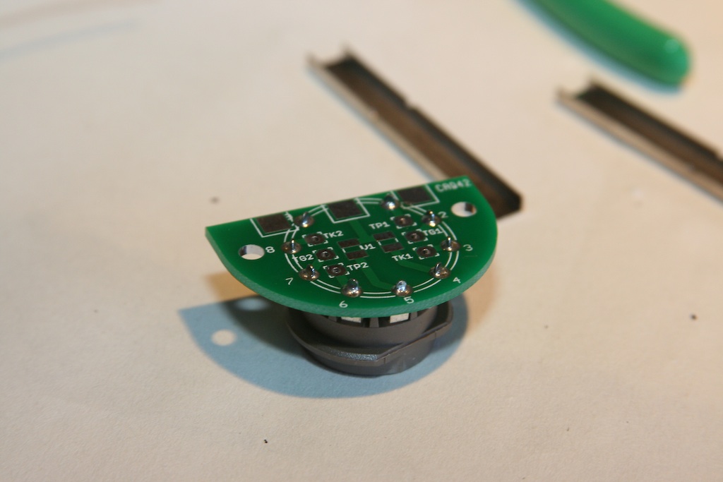
Another note: for those that scoff at paying extra for a real OSP tin finish, its projects with big pins where this really pays off. The plating is excellent on these boards, and the solder leaps from the iron and flows around these parts sooooo nicely.
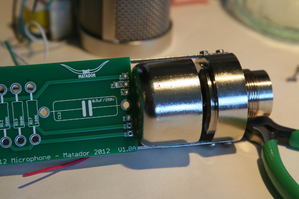
So here is where the first problem emerges: when I dimensioned the adapter board, I neglected to subtract the width of two side rails from the outside dimension. So it's like 1/16" too wide. This means that I have to loosen one of the mounting screws and bend the side rails out slightly to get it to fit. It's nice in a sense: it holds the board tightly for soldering! However I'll need to shave a little bit of each side so it's just right in the final version.
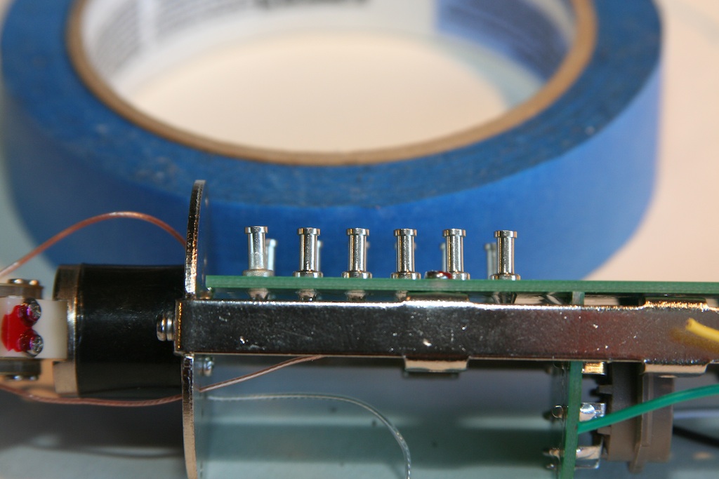
I need something to hold the board at a right angle: I just happened to have a DOA prototype board here, so why not?
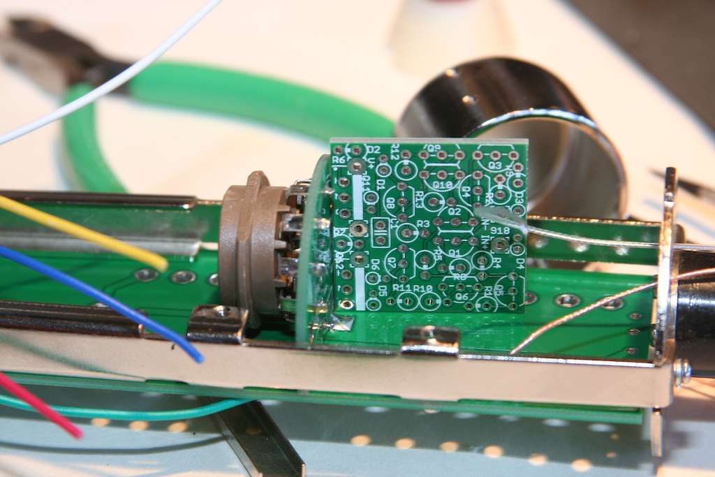
Easy to solder these tabs up on the front and back:
Plenty of clearance for the tube:
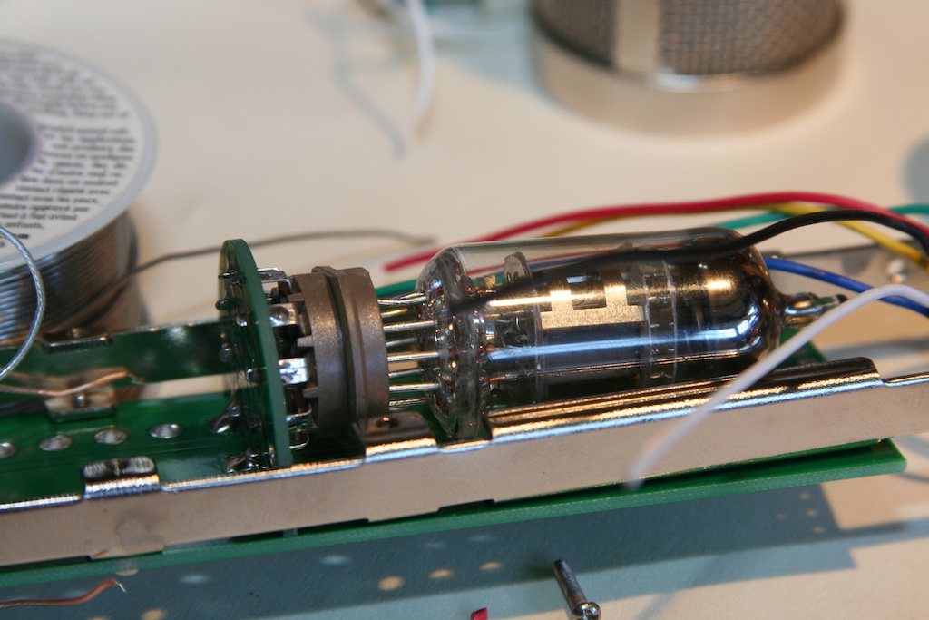
Time to start installing turrets! I made the holes slightly oversize (5 mils on each side), so this prototype board does not hold the turrets tightly. I blame Keystone, as their drawing gave conflicting information of what the proper PCB hole size was for these. Not too big of a deal, at least they fit.
There appears to be plenty of space between the shell and the turrets (about 1/2" by my estimation). This should give plenty of room for the components to sit up off of the board properly.
Until next time!
However as usual, Chunger's detailed drawings left nothing up to interpretation and all 4 mounting holes lined up exactly!
There is a good 1/4" gap between the bottom of the PCB and the top of the transformer housing, so no clearance issues there.
The next bit of nervousness: I had to draw the layout for the PCB tube socket based on a sketchy drawing. I made a few assumptions based on other sockets I had, and expanded the holes slightly so I had a bit of slop. But no problems here either: the PCB socket lined up perfectly.
So I flip this over and solder the socket down to the small adapter board.
Another note: for those that scoff at paying extra for a real OSP tin finish, its projects with big pins where this really pays off. The plating is excellent on these boards, and the solder leaps from the iron and flows around these parts sooooo nicely.
So here is where the first problem emerges: when I dimensioned the adapter board, I neglected to subtract the width of two side rails from the outside dimension. So it's like 1/16" too wide. This means that I have to loosen one of the mounting screws and bend the side rails out slightly to get it to fit. It's nice in a sense: it holds the board tightly for soldering! However I'll need to shave a little bit of each side so it's just right in the final version.
I need something to hold the board at a right angle: I just happened to have a DOA prototype board here, so why not?
Easy to solder these tabs up on the front and back:
Plenty of clearance for the tube:
Time to start installing turrets! I made the holes slightly oversize (5 mils on each side), so this prototype board does not hold the turrets tightly. I blame Keystone, as their drawing gave conflicting information of what the proper PCB hole size was for these. Not too big of a deal, at least they fit.
There appears to be plenty of space between the shell and the turrets (about 1/2" by my estimation). This should give plenty of room for the components to sit up off of the board properly.
Until next time!
tonycamp
Well-known member
Matador...nice job man, looks like it's going to be killer! also looks like you've been attending the Chunger school of photography ;D
Seriously excited about this project
thanx
Seriously excited about this project
thanx
chunger
Well-known member
Matador said:However as usual, Chunger's detailed drawings left nothing up to interpretation and all 4 mounting holes lined up exactly!
BOOM! I like it.
The Chinese Labor Camp would have filed the edges of the tube PCB though.. . HA! back-seat protyping. It's often funner than actually doing the work ;D.
A note I discussed with Matador earlier. I wanted to make sure this kit was able to be wired to utilize either half of the 2 triodes in the tube. As most are well aware, the C12's plate follower circuit grounds one of the triodes and it is not used in the circuit. Because NOS mic grade tubes are becoming rare, I thought it would be important if building a stereo pair of these mics to have the "left" and "right" mics utilize opposite halves of the tube. This way, if you periodically swap tubes from one mic to the other, you essentially double the service life of the tube. . . alternately, if building a single mic, you can swap the wiring over to the other half of the tube at some point and get the same life extension on the tube.
Quite a few companies advocate the ccda circuit that utilizes both halves of the tube like the stock HT-11A, but in this case, if the mics can sound fantastic with plate follower, I'm really keen on extending my tube life especially if dropping over $100/tube.
chunger
Well-known member
Hey Matador, quick un-related question. Can this PSU be utilized in a G7 build?
micaddict
Well-known member
Yup, it's official now.
2012 will go down in history as the year of the DIY classic tube microphone (PCB).
OK, Max/ioaudio's U47 circuit preceded it somewhat, but really got going this year. Poctop's U67 was right in it and Matador's C12 is well on its way in November.
And we were there when it all happened. 8)
Extra kudos to those who take the lead and actually make it happen. That includes chunger, of course.
Similar threads
- Replies
- 91
- Views
- 11K
- Replies
- 0
- Views
- 2K
- Replies
- 24
- Views
- 7K
- Replies
- 577
- Views
- 91K