[FEELER] C12 Clone Project

GroupDIY Audio Forum

Help Support GroupDIY Audio Forum:

This site may earn a commission from merchant affiliate links, including eBay, Amazon, and others.

Please indicate which project configuration would most interest you.

  • pcb's only

    Votes: 28 14.1%
  • pcb's and donor microphone

    Votes: 22 11.1%
  • partial kit (pcb, electronic components, transformer)

    Votes: 37 18.6%
  • partial kit with donor microphone

    Votes: 29 14.6%
  • complete turn-key package

    Votes: 83 41.7%

  • Total voters
    199
chunger said:
This is a plate follower circuit. . . same as original.  The discussion above was instigated by my suggestion to run opposite halves of the tube on stereo pair builds as an "advantage" of the plate follower circuit because it can extend the service life of rare NOS tubes.

If you want the CCDA type circuit, by all means, straight mods/optimizations to the stock Alctron HT-11A or Apex 460 PCB are well documented.

So we can make a C24 with an extended version of this circuit?  because that's something I'd like to do...
 
Just to make sure it's clear, I'll requote my answer from previous in the thread:

Matador said:
Enchilada said:
Good looking! Does this project follow on the original C12 schematic? I might be interested in replacing the PCB I etched for my C12 clone with one of these.

Kris

It's shamelessly a direct copy of the original AKG C12 schematic.  The reference designators for the mike are even the same.  ;)
 
IT'S ALIVE!

So I finally got everything buttoned up.  First order of business was to correct the power supply voltages.  Since I switched the design from half-wave to full-wave bridge, the B+ voltage was way too high.  I increased the RC filter resistors from 5K to 100K each.  I also increased the last filter resistor from 27K up to 33K.  This brought the loaded B+ from 250V+ down to 120V.  A 50K pot in the last filter spot would give enough adjustment range with multiple tube types so that seems like a good value.

To begin, I dialed down the bias voltage until it read -2V on the meter.  Then I connected the cables to the mike sans the capsule so that I could read voltages from various points:

1) Tube plate voltage: 81V
2) B+ supply at top of 100K plate resistor: 122V
3) Front diaphragm bias voltage: 61V.

So the tube is idling at about 0.4mA, which is consistent with the plate curves for this tube.  Much like when biasing a JFET, biasing the tube is a trade-off between gain and input signal swing.  I don't have a good idea of the output voltage/sensitivity of Tim's C12 capsule, so I picked a rough starting point of half of the bias range (e.g. -1V).

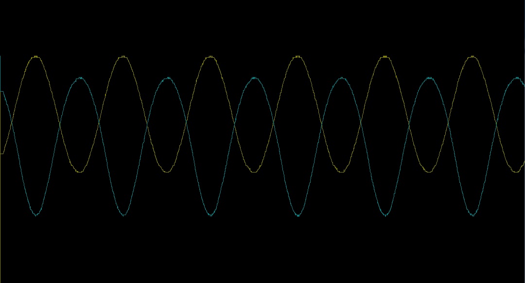
I then connected my signal generator between ground and the front backplate connection, which will inject a signal just prior to the 1000pF coupling cap leading into the tube grid.  I set my amplitude to be 500mV peak-to-peak, set my scope probes to AC coupling, then placed another probe right at the tube plate (just prior to the output coupling cap).  Here's what I see (I apologize for the unlabeled chart:  I took scope shots in the wrong format):

c12_waveform1.jpg


The yellow trace is the input, the blue the output of the plate.  You can't tell because it's not labeled, but the output signal swings about 14V peak-to-peak, which means gain is right around 28dB.  Maximum signal amplitude before clipping is about 1.2V.  Now the transformer will throw away about 20dB of gain so we need to be cognizant of that fact too.

One can get more gain by lowering the negative bias, which causes the quiescent current to increase.  So this may need some tweaking after a capsule is installed.

Next steps:  I'll install a new 6072A tube, make sure the voltages are still good, and then reinstall the stock Alctron capsule and make a few test recordings.  Assuming everything measures fine, I'll get Tim's capsule in there and we're ready for some studio time!
 
More for myself to remind me, but here are the list of changes between V1.0A and this design and V1.1.

PSU:

[list type=decimal]
[*]Change RC filter resistors from 5K to 100K
[*]Change 27K filter resistor to 3296W sized 50K potentiometer
[*]Change silkscreen to show B+ adjust point
[*]Change 0.1" connection headers to Pheonix contact 3.5mm screw terminals
[*]Change 47R dropping resistors to 4R7
[/list]

Microphone PCB:

[list type=decimal]
[*]Shift board down towards the transformer housing by 50 mils for top clearance
[*]Add 2 ground pads on tube adapter PCB
[*]Add silkscreen for connections to tube
[*]Shrink gap between resistors - give more clearance around 5000pF caps
[*]Shrink turret hole size by 10 mils
[/list]

If anyone else noticed something they'd like changed then now is the time to chime in!
 
Matador said:
One can get more gain by lowering the negative bias, which causes the quiescent current to increase.  So this may need some tweaking after a capsule is installed.

I don't think that's correct - this is a single stage grounded cathode amplifier.
Gain is not dependent on bias voltage or idle current. Or at least, not by much with common bias points.

You do vary gain by varying bias and current if you bias it somewhere on the curve where the curve bends a lot
ie. as in 'vari-mu' type operation.

In more usual bias schemes, gain is dependant on the tube type (mu, Rplate) as well as plate resistor and the load it is driving.

Bias voltage and idle current will affect headroom and THD (linearity) as well as plate dissipation and so on.

Unless I'm missing something relating to mics (which is entirely possibe :)  )
 
Remember to shave a little off the sides of the tube socket PCB to clear the mic rails.

Solder lugs and through holes for optional structural triangulating leads to strengthen tube socket PCB to main PCB connection.

Perhaps widen the traces on the psu pcb?  Make 'em nice and overkill.

We spoke of flipping the tube to occupy the upper portion of the mic in order to facilitate very large PIO options at C12 position if the turrets are installed to the back-side of the pcb.  This would require scooting the tube socket pcb down a bit and re-checking clearances particularly around the screw tab areas.

Perhaps widen the gap between turrets if we have space to spare?  C11, C10, C13 options would "widen" a bit.  Not that I know what those do, but I've seen some folks use esoteric stuff throughout.

I suggest stuff as usual with little understanding of actual function :p

I too like the chassis-mounted fuse option on the PSU, but we have real-estate to give an internally-mounted option.  I think that would be good to retain for those who do not like drilling as much as I do?

Next, and I say this only because I will be shooting this build. . . do we have PCB color options?  Green isn't bad at all, but I've greatly enjoyed the way the VC528's blue and the GDIY51X yellow PCB's come across on camera.  This in addition to the obvious sonic superiority of yellow.
 
Matatdor,

I also ripped out the 2 inner mesh layers of a replacement headbasket I bought from Dave Thomas @ Advanced Audio.  I was going to send the headbasket out to the factory that is doing my custom headbaskets, but decided to send them a complete HT-11A microphone instead so we can confirm exact fit prior to shipping the sample all the way across the world.

To be quite honest, I was trying to remove 1 layer of mesh, but the 2 inner layers ended up coming out.  This should give us a reference to hear meshing differences now while I wait for the sample of the custom headbasket to be made.
 
I was going to suggest a cool color for the pcbs. Blue or black would look great. It just makes it fun! Also I think overkill for PSU traces is a good idea as well. It will cost more but Its worth it to me...


Brice
 
chunger said:
Matatdor,

I also ripped out the 2 inner mesh layers of a replacement headbasket I bought from Dave Thomas @ Advanced Audio.  I was going to send the headbasket out to the factory that is doing my custom headbaskets, but decided to send them a complete HT-11A microphone instead so we can confirm exact fit prior to shipping the sample all the way across the world.

To be quite honest, I was trying to remove 1 layer of mesh, but the 2 inner layers ended up coming out.  This should give us a reference to hear meshing differences now while I wait for the sample of the custom headbasket to be made.

Cool, I'll was thinking of trying this surgery myself.  I'm curious to see how much of a difference it makes sonically.  How did you end up doing it?  Did you bake the entire thing or use a torch?

For colors, I always switch to black solder mask with yellow silkscreen for final versions of projects.
 
Neet. Matador I was curious if you redrew the C-12 schematic for this project? I know you followed it exactly, I just have a hard time reading and understanding the original akg schematic. If so do you mind posting it?

Thanks,
Brice
 
funkymonksf said:
Neet. Matador I was curious if you redrew the C-12 schematic for this project? I know you followed it exactly, I just have a hard time reading and understanding the original akg schematic. If so do you mind posting it?

Thanks,
Brice

The links to the re-drawn schematics are in the first page (at the bottom of the second post where I show the first panel layout).
 
Now it's REALLY alive!

First test with a real capsule

EDIT:

A few notes:

1) This circuit is NOT a good match for the K67 capsule (especially this cheap Chinese K67 copy I installed for testing):  the high end is very harsh, and it needs the negative feedback mechanisms of the U67 and U87 to tame it down.  This may be possible with a small cap from plate to the rear back-plate polarization supply like what the U87 does if someone is interested in trying that combination.  The ELA M251 trick of a 1000pF cap from plate to ground might also work, but that's cheating IMHO. ;)

2) This test was with an EH 6072A that was screened for noise and microphonics.  It passes the pencil tap test pretty well, and there is minimum tube blow noise in the background.  These are a great deal at about $18 a pop and there are a ton to be found.  It will be interesting to check out Chunger's variety of NOS tubes as well.
 
alexc said:
Matador said:
One can get more gain by lowering the negative bias, which causes the quiescent current to increase.  So this may need some tweaking after a capsule is installed.

I don't think that's correct - this is a single stage grounded cathode amplifier.
Gain is not dependent on bias voltage or idle current. Or at least, not by much with common bias points.

You do vary gain by varying bias and current if you bias it somewhere on the curve where the curve bends a lot
ie. as in 'vari-mu' type operation.

In more usual bias schemes, gain is dependant on the tube type (mu, Rplate) as well as plate resistor and the load it is driving.

Bias voltage and idle current will affect headroom and THD (linearity) as well as plate dissipation and so on.

Unless I'm missing something relating to mics (which is entirely possibe :)  )

The operating point of this design is down near the bottom where mu varies a lot with plate current.  We have a quiescent point down near 0.3mA and a VPP of only 120V.  I can see significant gain changes as the bias point is changed up and down.  I suspect much like a JFET, the transconductance of the tube varies significantly as a function of current in this region.
 
manulaudic said:
Which capsule is the test capsule?
M

Not sure exactly:  I pulled it from an MXL2003 some number of years ago, and now it serves as my test beater capsule.  There's actually fingerprints on it, and it came from the factory with solder spittle on it. ;)  No matter how hard I try to kill it, it always seems to work.

It looks like any number of K67 clones as sold by WGT, Ningbo Tongxin, etc.
 
chunger said:
I too like the chassis-mounted fuse option on the PSU, but we have real-estate to give an internally-mounted option.  I think that would be good to retain for those who do not like drilling as much as I do?

As far as I'm concerned, if you haven't had to pull metal shavings out of your eyeballs with a fine pair of tweezers, then you haven't truly experienced DIY. ;)
 
The operating point of this design is down near the bottom where mu varies a lot with plate current.  We have a quiescent point down near 0.3mA and a VPP of only 120V.  I can see significant gain changes as the bias point is changed up and down.  I suspect much like a JFET, the transconductance of the tube varies significantly as a function of current in this region.

Thanks for clarifying - I did see my ccda circuit biased way down low like this too. I took it up to 147V, 0.5mA and still felt that it was operating in quite a non linear region.

Just out of interest, do you know why this particular bias region would be chosen in the C12?

I mean low plate voltage can be advantageous (safety not least) and low hv power also.
And given the voltage swings required are relatively small so should minimise distortion.
Maybe also to extend tube life.

It just seems to a tube mic layman that it is very starved current design operating in a non linear region.

Thanks and great work btw. :)
 

Latest posts

Back
Top