Frank's Pultec Support

GroupDIY Audio Forum

Help Support GroupDIY Audio Forum:

This site may earn a commission from merchant affiliate links, including eBay, Amazon, and others.
I gave up on V 1.6, too much trouble.
I am back to V 1.4. I have unity gain now in bypass mode, cause I changed the resistor 18k to 39k on the gainboard.
High boost and cut are working fine.
But:
Lowboost is only around 9-10dB, Lowcut around 25dB.
I wonder if somebody else who builded this version 1.4 has same results in the low band.

I really would like to know if you have a low boost of around 14dB :)

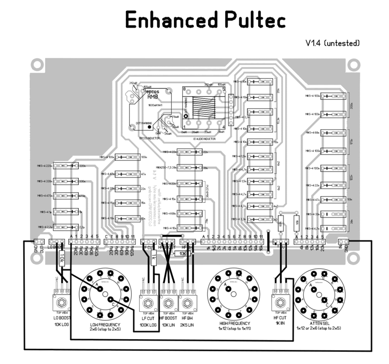
Modifications were done like this:
Pultec15wiringcorrected.gif

 
Andreas Pfeiffer said:
I wonder if somebody else who builded this version 1.4 has same results in the low band.

I'm building version 1.4 here. I've found it's not exactly the original Pultec schematic that was followed here.
Also, Gyraf's version is also not like the original schematic (see link but disregard cap & inductor values).

http://www.recproaudio.com/diy_pro_audio/diy_files/eqp_1a/eqp1a_filter_schematic.jpg

So basically I'm going to hack the 1.4 board and make it like the original.  It will mean cutting traces and adding some resistors.
 
Could use some help here...

I'm building a 'hybrid' version of the enhanced Pultec. Hybrid meaning that I want to make it switchable between a classical and clean version.
Like this:
Classic: XLR in  -> edcor WSM600/600 transf. -> enhanced filter section -> EQP1A makeup amp with a 2520 DOA -> edcor WSM600/600 transf. -> XLR out
IC: XLR in  -> enhanced 5534 unbalancing -> enhanced filter section -> enhanced amp and 5534 balancing -> XLR out

I made the 'switchboard' with 5 relays and this seems to be working fine but there are some problems:
The EQ seems to be working different in both circuits. The classic version seems to be working more or less normal.
But I can never get enough low boost on the IC-version. And the Low cut is too much on the IC-version. (which seems to be exactly the same as others reported)

I've experimented a lot and the problem seems to lay in the combination of the filter and makeup amp.
With an output straight after the filter both circuits act the same.
And only the amp-section (with the filter bypassed) also seems to work as it should. But the filter and amp combined doesn't.
I'm guessing the filter doesn't like the impedance of the IC based make up amp. I know the Pultec filter section is designed around a 600 ohm input load, but I'm not sure about the output load.
Anyone ever got this enhanced pultec to work correct with the Franks make up amp?


(and yes I'm using the 1.4 version of the boards but made all the mods to resemble the original Pultec filter section)
 
I'm still working on mine so I can not share any experiences.
However, I've found that the enhanced filter board is not the same as any pultec schematic I've seen.
So this could be a reason for this strange behaviour.
Also, when using the edcor transformer, did you add a 620R resistor to ground on the input of the filter just like the original Pultec has?
 
Isn't the enhanced board based on a manley?
I can't spot that many differences to the original, except the added frequencies. Just add the resistors per the correct wiring and you should be ok.
 
radiance said:
I'm still working on mine so I can not share any experiences.
However, I've found that the enhanced filter board is not the same as any pultec schematic I've seen.
So this could be a reason for this strange behaviour.
Also, when using the edcor transformer, did you add a 620R resistor to ground on the input of the filter just like the original Pultec has?

If you follow the mods posted earlier you'll get pretty close to the original pultec filter. There are still some small differences but I also altered these and it doesn't make that much difference.
I've tried with and without the 620 ohm resistor across the secondary of the input transformer. This doesn't make that much difference either and it's the circuit without transformers (Franks version) I'm having trouble with anyhow.

Nele said:
Isn't the enhanced board based on a manley?
I can't spot that many differences to the original, except the added frequencies. Just add the resistors per the correct wiring and you should be ok.

The Manley enhanced pultec has a tube make-up amp so the concept is a bit different.

So can anyone actually confirm it's possible to make the lows boosts and cut about 14dB with Franks version?
 
Hank Dussen said:
So can anyone actually confirm it's possible to make the lows boosts and cut about 14dB with Franks version?

What I'm doing is hack Franks board and make it exactly like the Gyraf Puoltec Filter schematic.
I've used this before in a solid state Pultec and with that it's possible to get the 14dB cut and boost.
I don't see why it would not be possible with Franks board...
 
In my experience with (mainly solid state) pultecs, this is normal.    The low boost and cut are known to have different slopes, that's the whole reason for the simultaneous low cut/boost pultec effect. 

Check the original EQP manual and the Manley one, (they both have frequency plots), you'll see this.   

Andreas, I have no idea what the problem is with your low boost (9-10dB) being very low, check the 620R like has been said before as well as make sure you haven't switched your pots around... seems I do that almost every time!  ;D

hope you sort your filters out.
 
Here are some pics that show the different curves of the 2 solid state versions:

Mind you they share the filter board, the only difference is the balancing/debalancing and the make-up amp.
As mentioned before the 'classic' version uses a transformer (Edcor WSM600/600) for balancing/debalancing, and the classic make-up amp based on an 2520 discrete opamp.
The 'IC' version is Franks circuit with 5532 opamps.

First pic shows curves for 60Hz full boost.
The green line is the Franks version.
 
Third pic shows curves for 60Hz full boost without the make-up amp. So an unbalanced output directly after the filter.
Now you can see it's (more or less) exactly the same! If I cut I get the same results.

Which makes me draw the conclusion that the filter doesn't like the 5532 based make-up amp.
I'd love to be wrong and/or be able to fix this!
 
That is odd. I haven't used these 5532 stages you are using unfortunately, and I don't want to lead you to chasing your tail, but have you tried different values for the 10K and 1K resistors at the filter output?
 
EVERYTHING IS WORKING NOW Very Happy (with the excellent help from a friend)
The resistor at the LF CUT had to be changed from 1k to 10k. After that the low gain and cut worked as they should.
 
Can any body explain what the 10K resistor to ground is for?
http://img.photobucket.com/albums/v426/brio/Pultec15wiringcorrected.gif

That's not there in the original Pultec schemo....
 
You mean the one horizontal on the PCB? Looks like the trafo load R, 620R in the original.
 
Thanks Mitsos!

Hank Dussen said:
IC: XLR in  -> enhanced 5534 unbalancing -> enhanced filter section -> enhanced amp and 5534 balancing -> XLR out

Have you tried this configuration without the 10K to ground resistor?

O, and a schematic from that 5534 un/balancing stage would help so we know what we're talking about.
 
mitsos said:
You mean the one horizontal on the PCB? Looks like the trafo load R, 620R in the original.
this was probably there to provide a load for the 5534 driver as that didn't use a input transformer. just leave it out when using original config. i'll search for the schematic..
 
radiance said:
Thanks Mitsos!

Hank Dussen said:
IC: XLR in  -> enhanced 5534 unbalancing -> enhanced filter section -> enhanced amp and 5534 balancing -> XLR out

Have you tried this configuration without the 10K to ground resistor?

O, and a schematic from that 5534 un/balancing stage would help so we know what we're talking about.

I don't think there's a schematic of this 5532 un-/balancing/amp stage.
I've tried without the 10K resistor. Doesn't seem to make any difference.
I'm doing some more tests...
 

Latest posts

Back
Top