You are using an out of date browser. It may not display this or other websites correctly.
You should upgrade or use an alternative browser.
You should upgrade or use an alternative browser.
Gates SA-39B from scratch
- Thread starter DaveP
- Start date


Help Support GroupDIY Audio Forum:
This site may earn a commission from merchant affiliate
links, including eBay, Amazon, and others.
Thanks Gato,
I use a Rode NT1-A mic, into a non feedback mic pre I made myself. It then goes into an LA-2D I made (the D is because it uses green LED's to light the variable resistors). All the circuits are somewhere on this forum. The reverb is the stock Plate setting on my Yamaha AW16G Digital Desk.
best
DaveP
Bowie
Well-known member
- Joined
- Jun 22, 2012
- Messages
- 369
Sounds wonderful. I like that it has your own personality inflected in it. Challenging song to cover because the mood has to be conveyed in a convincingly. You did it justice.DaveP said:Ok, this is what has held up production.
http://soundcloud.com/delayed-action/where-are-we-now
We are now green for go, more pics Monday and Tuesday.
best
DaveP
Would love to see some more pics of the SA39 as it progresses. If you, by chance, feel like drawing up a layout, I would be all over a project like this.
Thanks Bowie,
It certainly was challenging, made me realise just how good he is. Reading about his recordings in the book Pucho recommended, I found out he only ever does one take on his vocals!
Anyway back to topic:
I am making progress on the chassis and pics will be posted today. I am letting logic dictate the layout, so I'm working it out as I go along.
best
DaveP


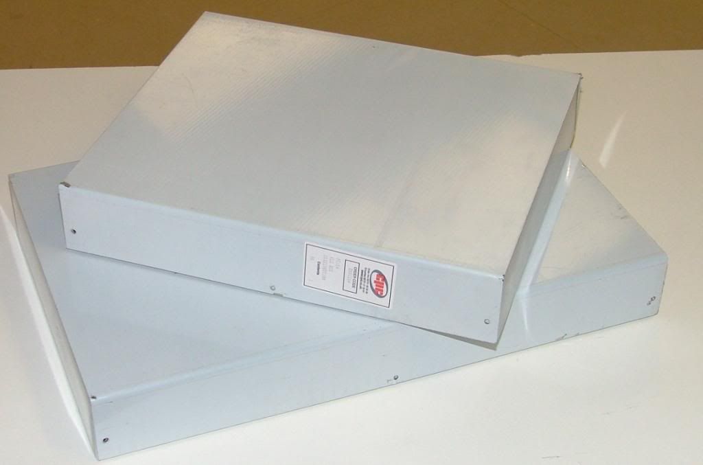
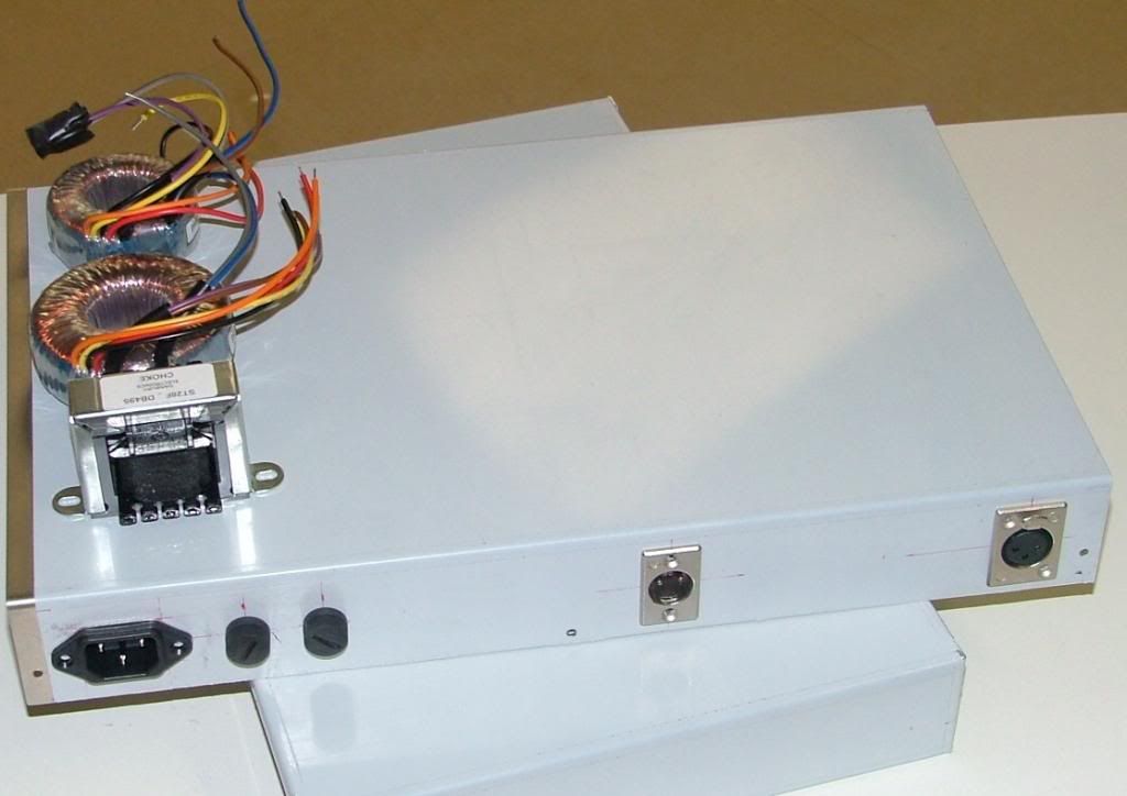
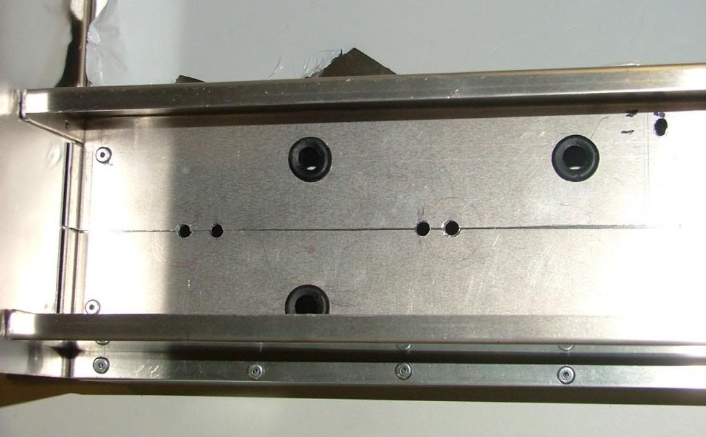
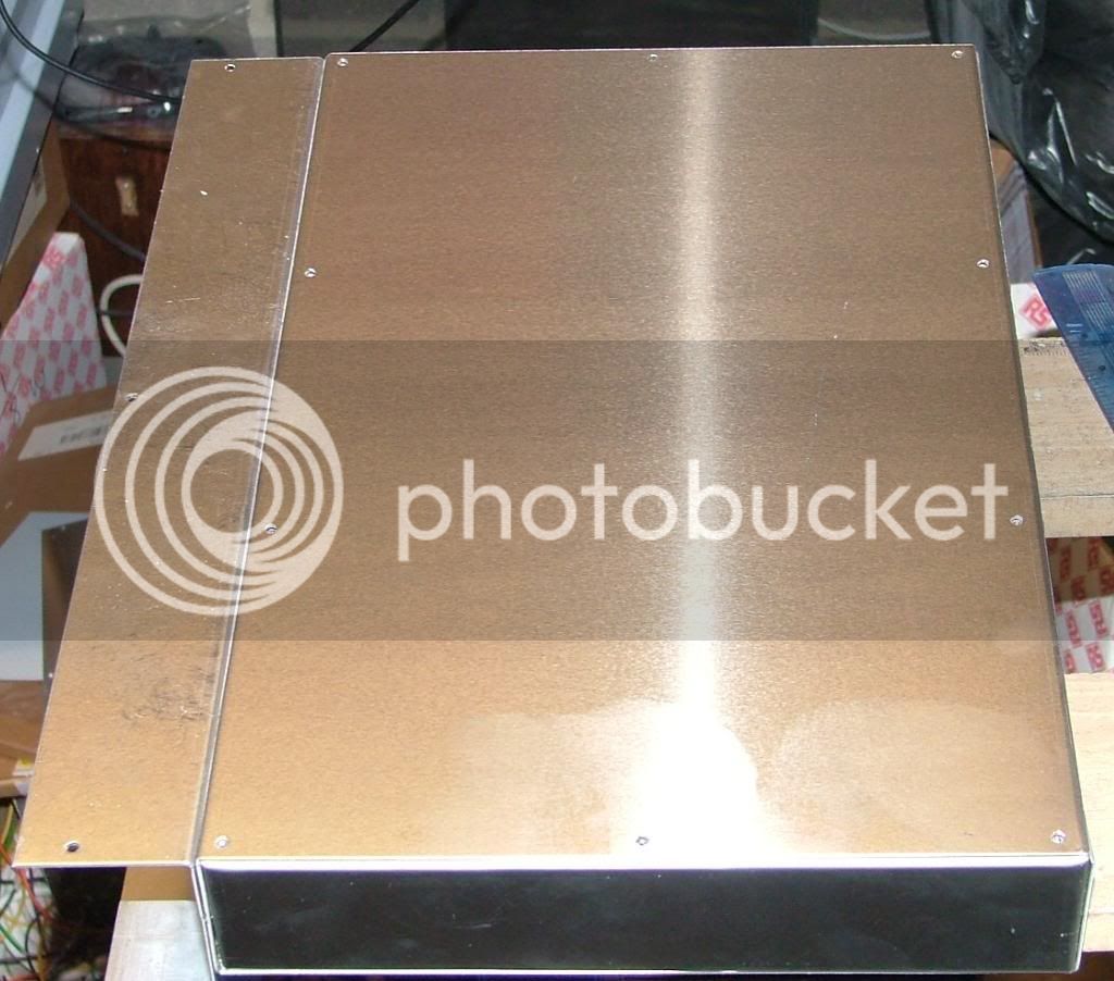
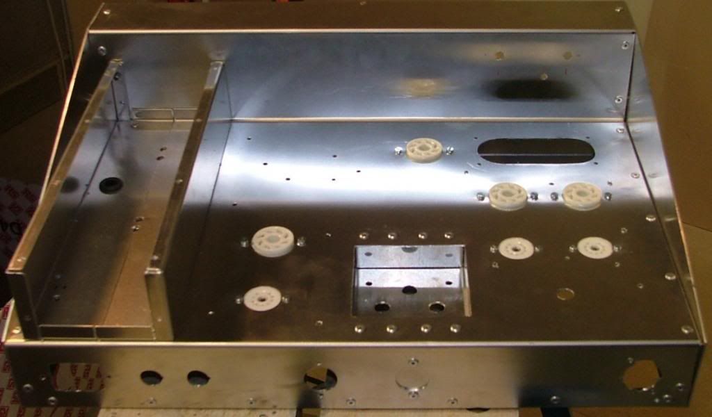
This is all about the chassis construction.
I start with ready made boxes from CPC in UK, no point in reinventing the wheel.
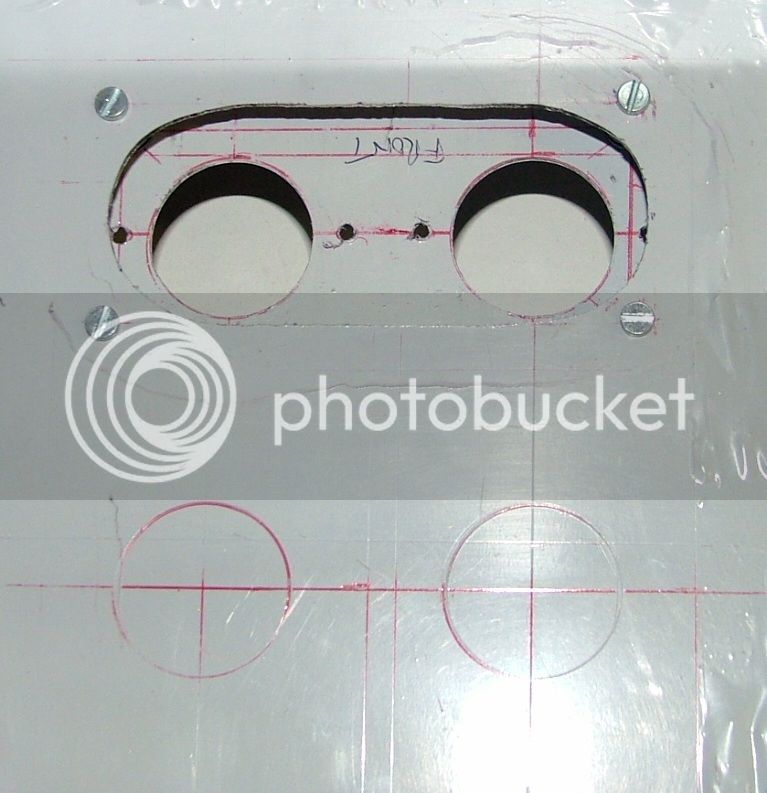
The back panel cut out for sockets and fuses.
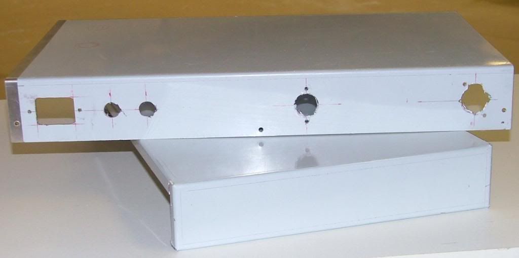
This is with them fitted and showing Transformer and choke positions on top.
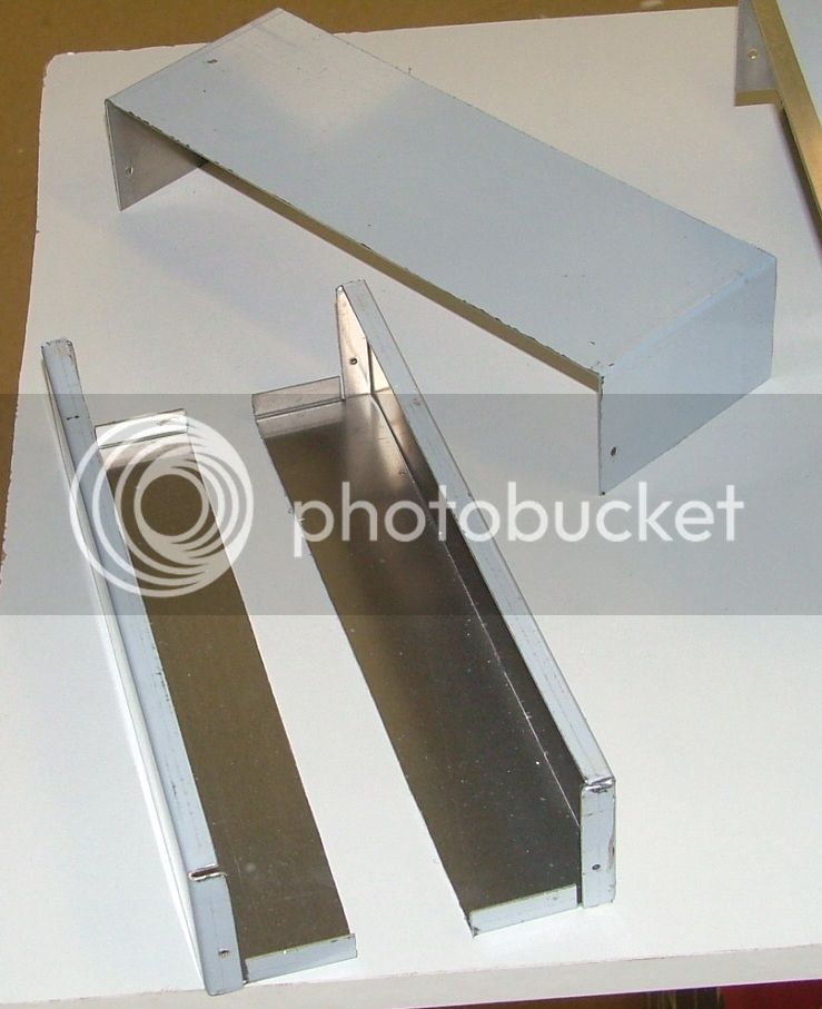
The smaller box in the first pic is cut to size to make a neat safety cover.
More soon.
DaveP
I start with ready made boxes from CPC in UK, no point in reinventing the wheel.
The back panel cut out for sockets and fuses.
This is with them fitted and showing Transformer and choke positions on top.
The smaller box in the first pic is cut to size to make a neat safety cover.
More soon.
DaveP
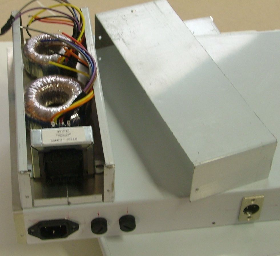
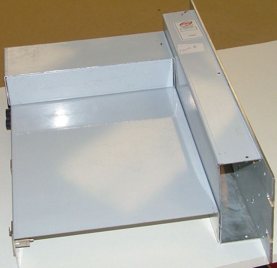
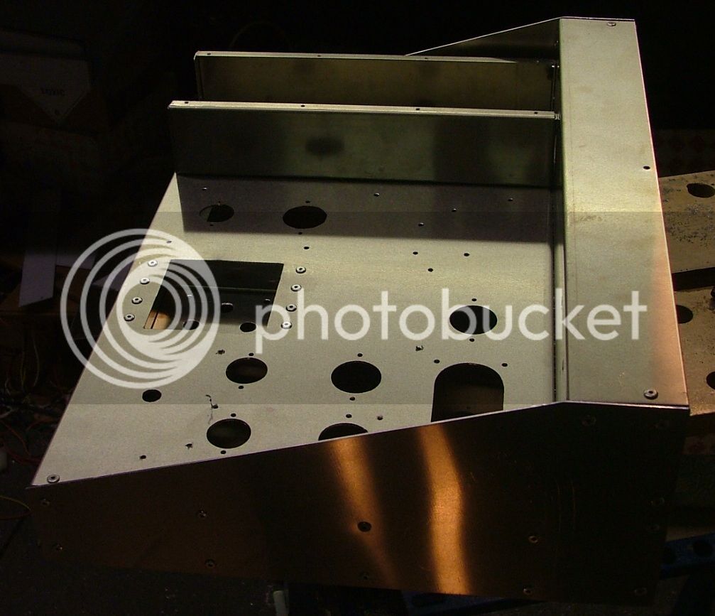
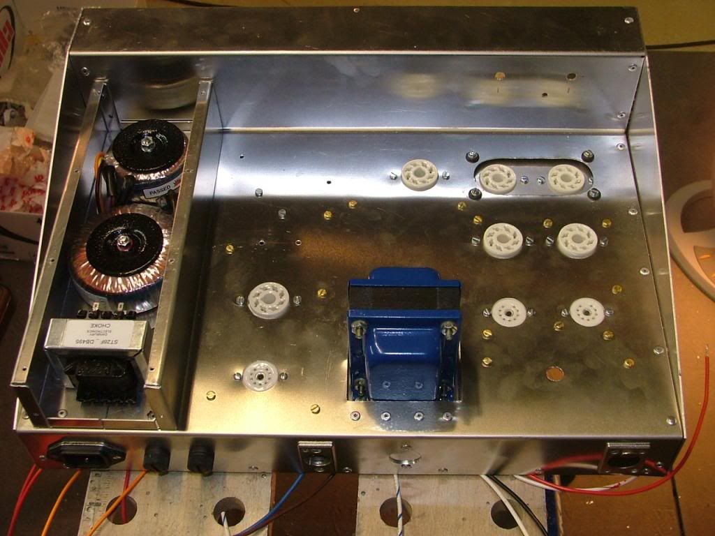
The Transformers and choke fit neatly and safely inside the box, fixing holes will be drilled for a second set of toroids on the inside to save space, grommets will be fitted for the wires.
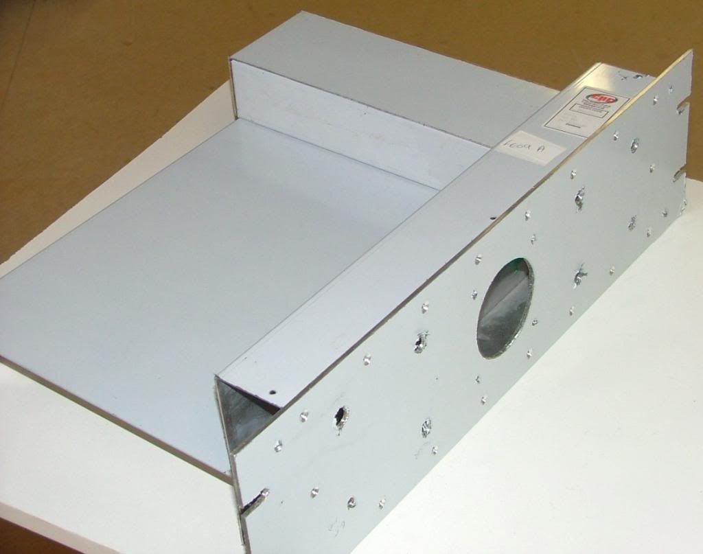
This is how it will look from the side, there will be reinforcing side panels to take the weight.
Front view....
Next job is to sort out the tube positions and in and output transformers.
best
DaveP
This is how it will look from the side, there will be reinforcing side panels to take the weight.
Front view....
Next job is to sort out the tube positions and in and output transformers.
best
DaveP
justanalogue
Well-known member
True multitasking craftsmanship!
Chapeaux.
Willem.
Chapeaux.
Willem.
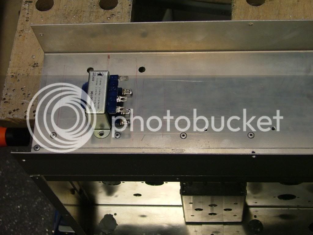
Chassis Assembly:
Finally worked out what I hope will be a good layout.
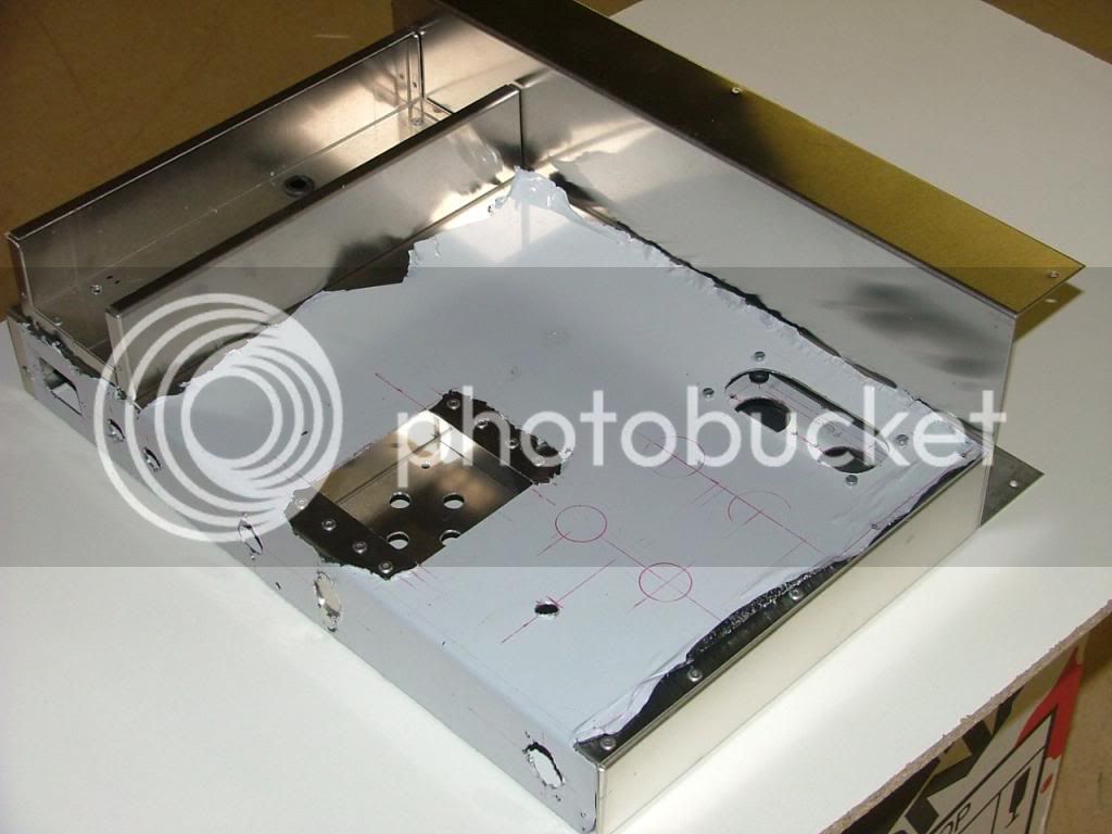
Some tube positions still to do, but they can wait.
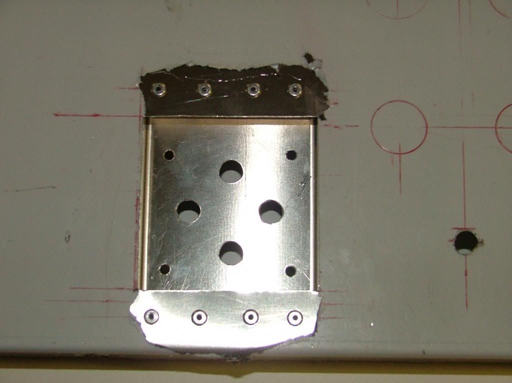
The 6L7's are shockmounted to reduce microphonics.
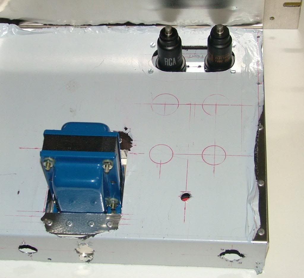
The Edcor is too high for 3u so had to recess with a spare box.
This is how they fit
Inside view
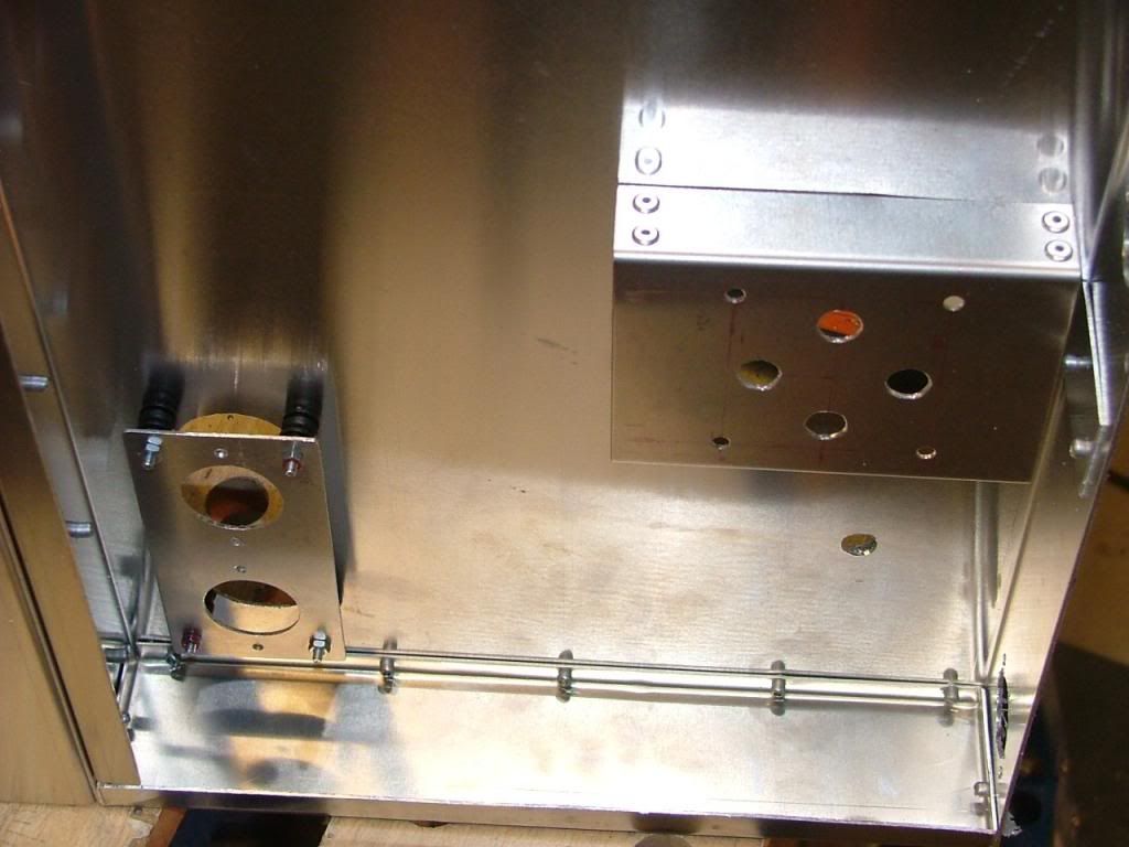
External TX case fitted and grommeted for wires.
Front panel now with fixing brackets
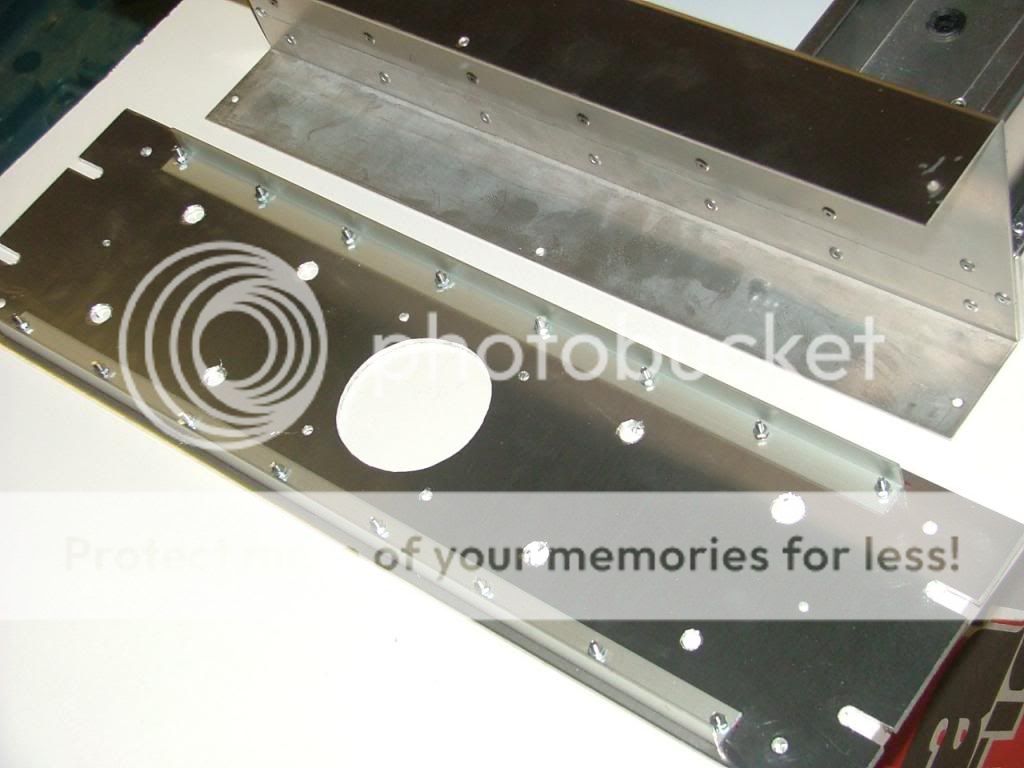
The chassis is almost finished now, there are re-inforcing side panels to make and the removable base panel, then comes the fitting of the main parts, more next week.
best
DaveP
Finally worked out what I hope will be a good layout.
Some tube positions still to do, but they can wait.
The 6L7's are shockmounted to reduce microphonics.
The Edcor is too high for 3u so had to recess with a spare box.
This is how they fit
Inside view
External TX case fitted and grommeted for wires.
Front panel now with fixing brackets
The chassis is almost finished now, there are re-inforcing side panels to make and the removable base panel, then comes the fitting of the main parts, more next week.
best
DaveP
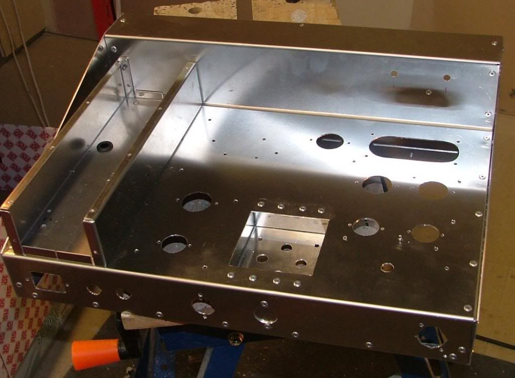
The chassis is almost done now and will be finished completely tonight, its not the metal work that takes the time, its sorting out the best layout compromise.
This is the top view
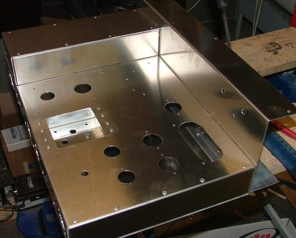
This shows the positions of all the tubes including regulator and 6H6, I've also made the holes for the top grid screen wires.
Inside view, all the fixings for the Caps and Tag strips are drilled.
Base Cover
This is where the Input TX is going
It's screened from the rest of the amp.
Thats it for now, final chassis pix tonight.
best
DaveP
This is the top view
This shows the positions of all the tubes including regulator and 6H6, I've also made the holes for the top grid screen wires.
Inside view, all the fixings for the Caps and Tag strips are drilled.
Base Cover
This is where the Input TX is going
It's screened from the rest of the amp.
Thats it for now, final chassis pix tonight.
best
DaveP
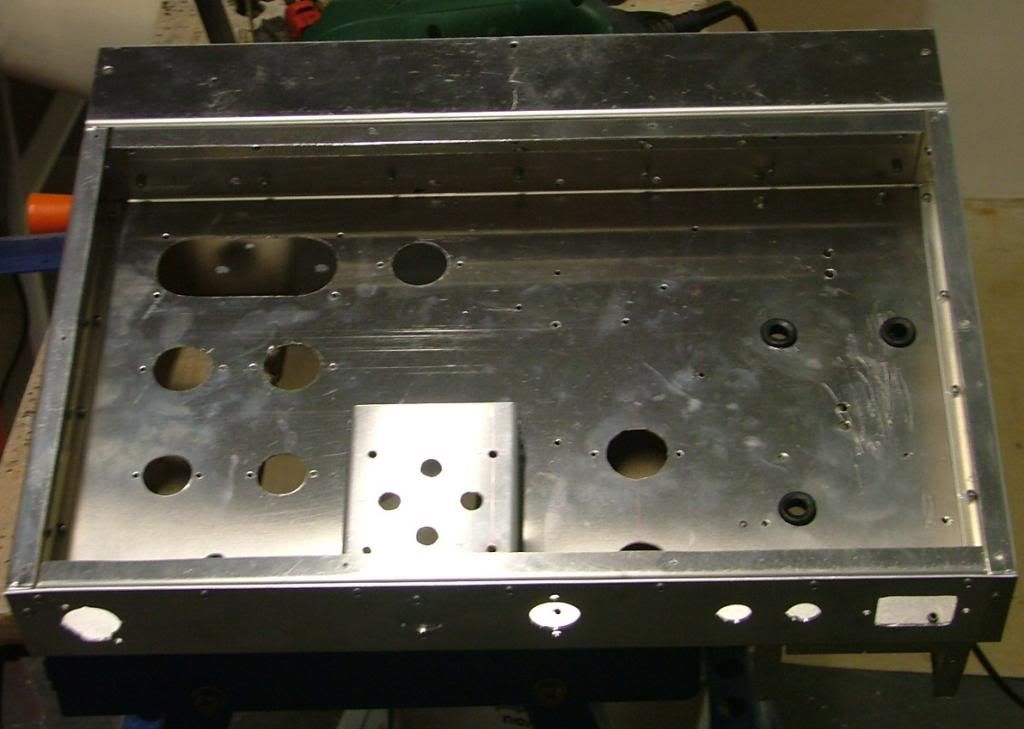
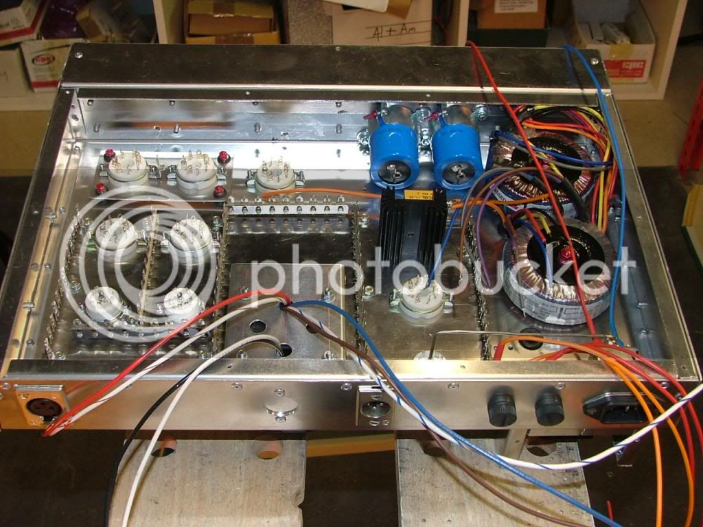
The Chassis is now finished, I fitted some reinforcing side panels to take the weight of the transformers.
You can now make out the layout,
6L7's on the suspended plate at front, close to the input TX behind the screen, followed by 6SJ7's then the 6S4 output triodes; the TX in its recess. At the front centre is the 6H6 diode near to the timing components behind the screen. On the left hand side are the ECC83 and 6W6GT regulator tubes.
Started fitting the hardware, thats most of the tube bases, things should move up a gear now and all the rest of the main lumps will be fitted next week, and maybe even some components.
best
DaveP
MagnetoSound
Well-known member
Lovin' it, Dave. You are inspiring me to do a lot more work with my pop riveter.
All major parts now fitted including all the tag strips.
Inside view, pre-wired some parts before fitting, learnt that one the hard way.
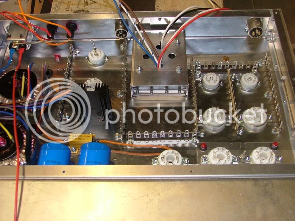
Heatsink fits nicely between top and base, its for the DC supply schottky Diodes.
Earth/ground Bussbar fitted, all earths will be connected to this for star grounding.
This shows detail of basic shockmount for 6L7's. Its not perfect but its got to be better than direct fixing to chassis
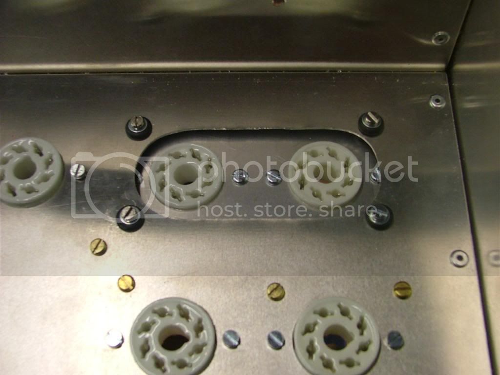
Its just 2 grommets on each corner with a loose fit nut and bolt through the middle, there is thus no metal to metal contact and the earth will have to be run separately, there will also be the heater wires, grid wires and other wiring to increase the damping.
more tomorrow.
best
DaveP
Inside view, pre-wired some parts before fitting, learnt that one the hard way.
Heatsink fits nicely between top and base, its for the DC supply schottky Diodes.
Earth/ground Bussbar fitted, all earths will be connected to this for star grounding.
This shows detail of basic shockmount for 6L7's. Its not perfect but its got to be better than direct fixing to chassis
Its just 2 grommets on each corner with a loose fit nut and bolt through the middle, there is thus no metal to metal contact and the earth will have to be run separately, there will also be the heater wires, grid wires and other wiring to increase the damping.
more tomorrow.
best
DaveP
MagnetoSound
Well-known member
Dave, this is looking great! Just love the screening box.
Still working on this every week but not so much to show for it.
This pic shows the start of the earth/ground busbar, the HT rectifier bridge and caps, the revised heatsink position and connection, the bracket for the 6L7 balance pot, all the transformer connections.
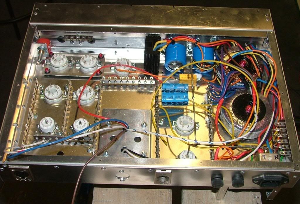
None of the cables have been clipped up yet, as its best to tidy them up when all the wiring is finished.
The DC supply for the main tubes is finished and ready to wire, the aux supply for the elevated regulated supply is still to finish but that is just AC.
This is the power supply schematic;
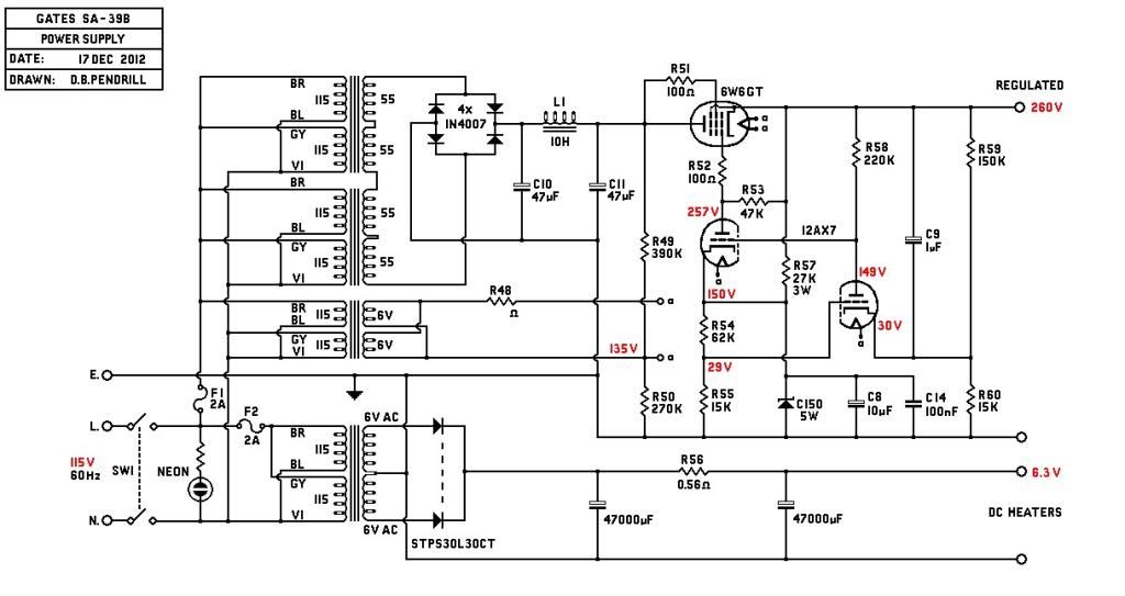
As you can see, its quite busy and it needs a clear head to avoid mistakes.
This one is wired for 115V as its going stateside.
The back of the front panel?!? is drilled and grommeted to take the power switch wiring and the screened signal cables, input TX is carefully sited between all the switches of the front panel. More holes will be drilled as and when required.
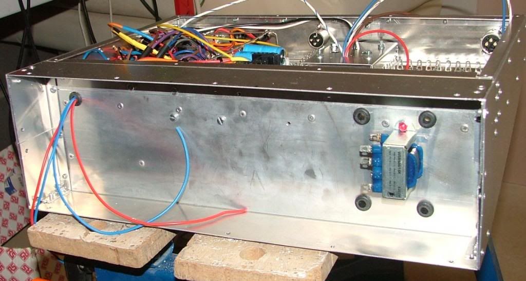
Next week the tubes will be wired and fired up and dropping resistors settled.
best
DaveP
This pic shows the start of the earth/ground busbar, the HT rectifier bridge and caps, the revised heatsink position and connection, the bracket for the 6L7 balance pot, all the transformer connections.
None of the cables have been clipped up yet, as its best to tidy them up when all the wiring is finished.
The DC supply for the main tubes is finished and ready to wire, the aux supply for the elevated regulated supply is still to finish but that is just AC.
This is the power supply schematic;
As you can see, its quite busy and it needs a clear head to avoid mistakes.
This one is wired for 115V as its going stateside.
The back of the front panel?!? is drilled and grommeted to take the power switch wiring and the screened signal cables, input TX is carefully sited between all the switches of the front panel. More holes will be drilled as and when required.
Next week the tubes will be wired and fired up and dropping resistors settled.
best
DaveP
Similar threads
- Replies
- 1
- Views
- 770
- Replies
- 1
- Views
- 790