You are using an out of date browser. It may not display this or other websites correctly.
You should upgrade or use an alternative browser.
You should upgrade or use an alternative browser.
Gates SA-39B from scratch
- Thread starter DaveP
- Start date


Help Support GroupDIY Audio Forum:
This site may earn a commission from merchant affiliate
links, including eBay, Amazon, and others.
Thanks Magnus,
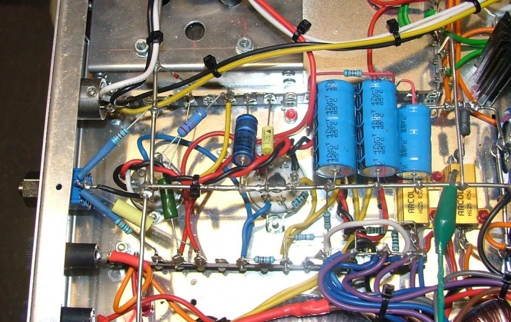
Well into the wiring up now, the DC heater supply is finished and the tubes light up ok at 6.3V, had to trim the dropping resistor with a 0.1 ohm to bring it down ok. Hard wiring always has less resistance than croc clips so even 0.1 ohms has an effect at 2.7A
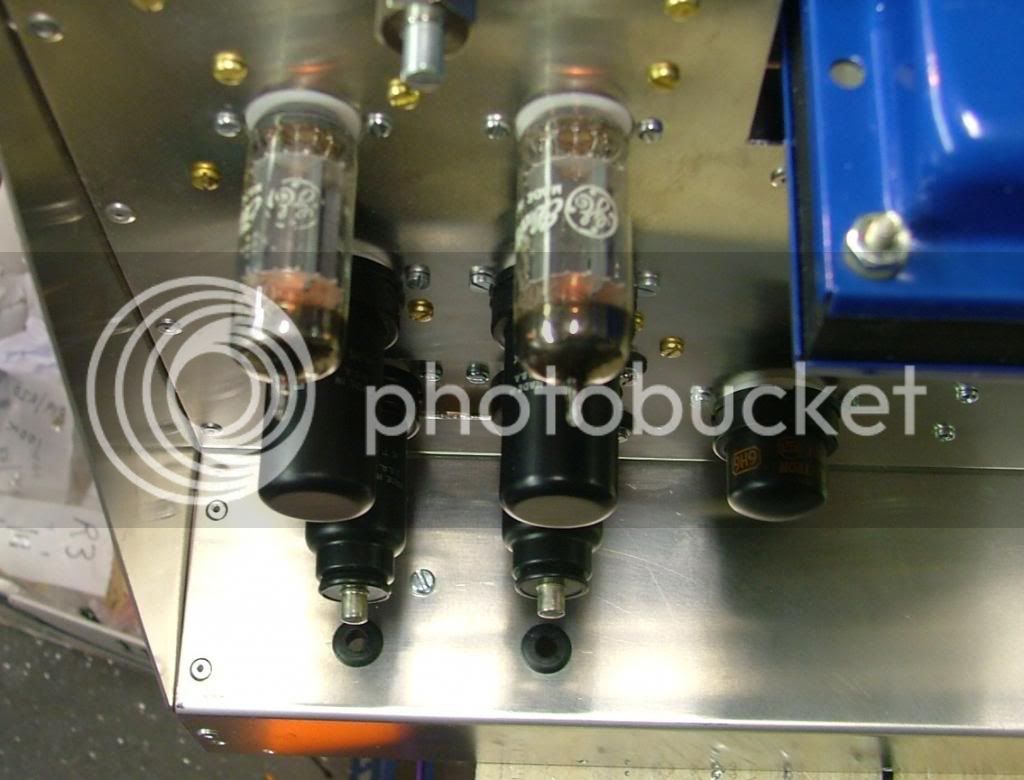
All of the grounding Busbar is now in and the output TX is wired up as are most of the coupling caps, all Polyprop no less.
It will look a lot tidier once the wires are nicely clipped.
Thats my lot for now
DaveP
Well into the wiring up now, the DC heater supply is finished and the tubes light up ok at 6.3V, had to trim the dropping resistor with a 0.1 ohm to bring it down ok. Hard wiring always has less resistance than croc clips so even 0.1 ohms has an effect at 2.7A
All of the grounding Busbar is now in and the output TX is wired up as are most of the coupling caps, all Polyprop no less.
It will look a lot tidier once the wires are nicely clipped.
Thats my lot for now
DaveP
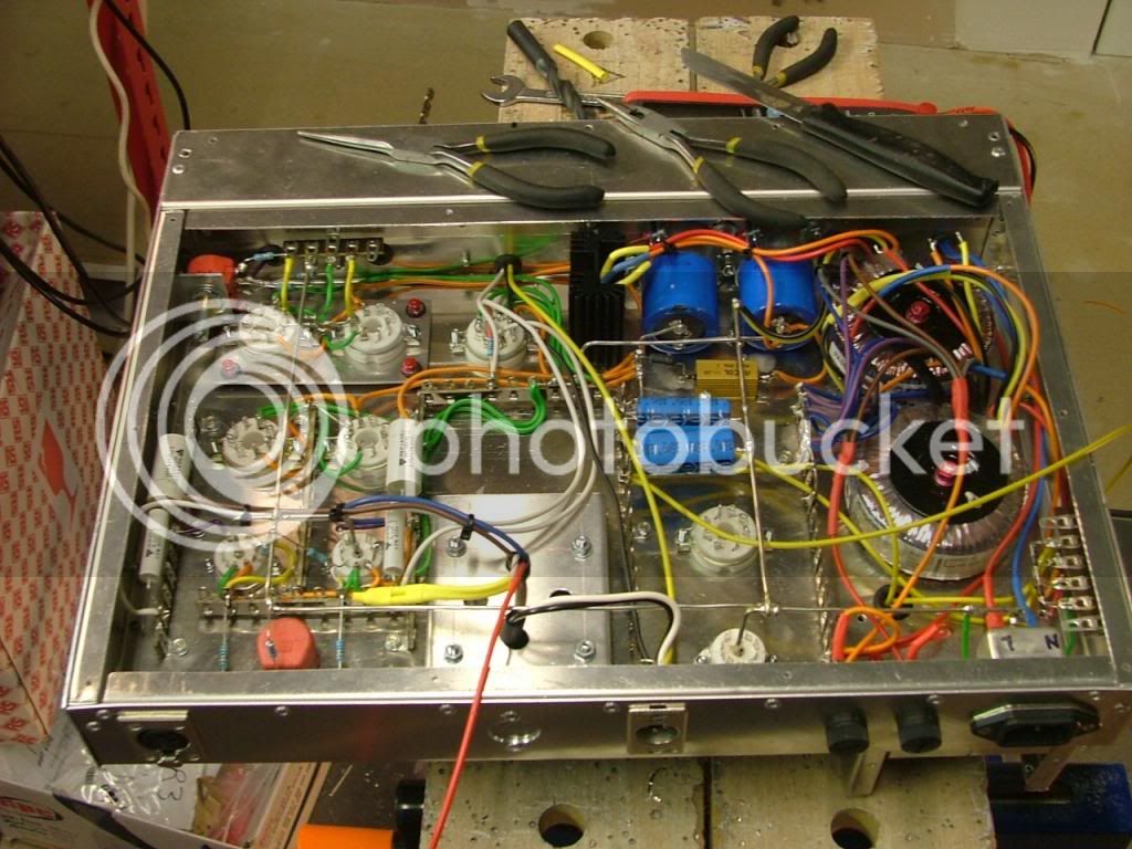
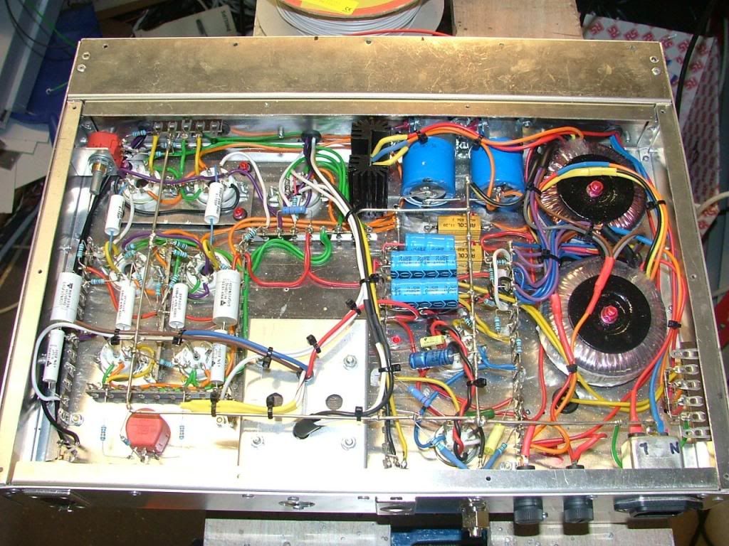
The comp amp has now been fired up and no smoke! All the components are in place and voltages are ok.
All the little shiney specs are bits of flux, this is the first time I've used lead free solder, its a bit harder to melt but leaves a nice shiny finish, I'll have to brush them all out later.
There is a problem with the regulator, its far too twitchy and can often stall on switch on. I'm replacing the ECC83 with an EF80 pentode in a more conventional circuit. Taking a break now so will take up reins again 2nd week of April.
best
DaveP
letterbeacon
Well-known member
It looks fantastic -great work!
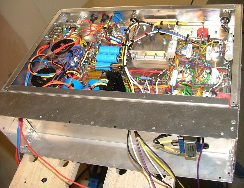
Ok, back on the case.
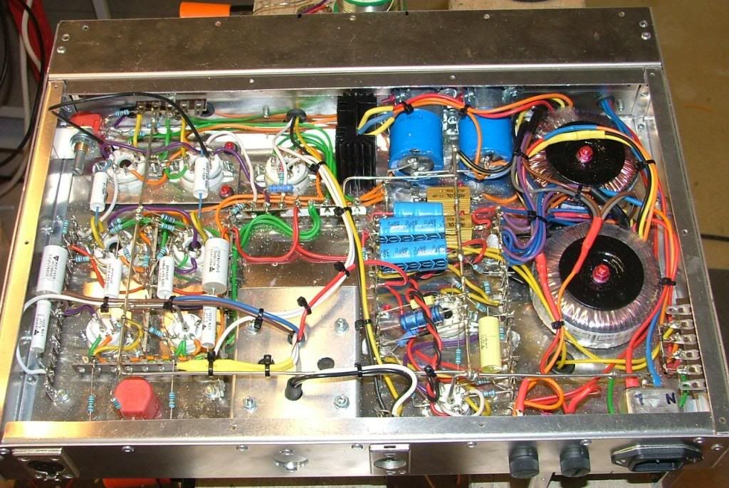
I think the regulator needs to be fed from the unreg side or it stalls, but in any case I decided to revert to a trusted design.
I decided to redesign the Fairchild regulator for 260V, but using a couple of Zeners instead of the 5651 tube as it takes up more space. I had an EF80 to use instead of the 6084/E80F, it was just a question of changing the operating point to work for 260V.
The Zeners have to have the correct current through them to regulate properly so that sets the feed resistors for the g2 voltage.
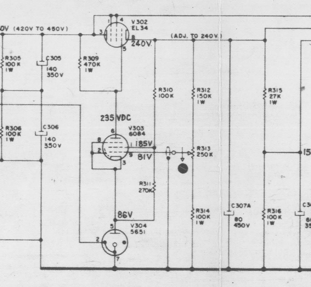
Once the cathode voltage is set, you have to work out the values of the control resistor string to get you some adjustment of the g1 voltage below the cathode voltage. The operating point of the pass tube, I'm using a 6W6GT, is going to be several volts below the regulated voltage so its ~255V. The voltage from the B+ supply is ~350V so the plate resistor is dropping 95V. We need high gain so a 220k res gives ~0.5mA plate current. The g2 voltage needs to be ~200V and the Zeners need ~5mA so this gives us a 12k res. The Zener dropper res is 200V - Vk 86V / 5mA which is 22k. Thats how I arrived at the Regulator design,
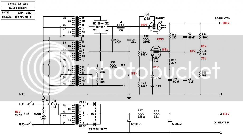
The heater supply is elevated to 156V to within the spec of the tubes Vk:heater Voltage.
Caps across the Zeners keep it steady and filter hash.
Bypass cap from 260V feeds ripple to grid to cancel.
You have to work out the power rating of all the resistors, so the 22k is 3W and the 12K 7W which are values I had in the box.
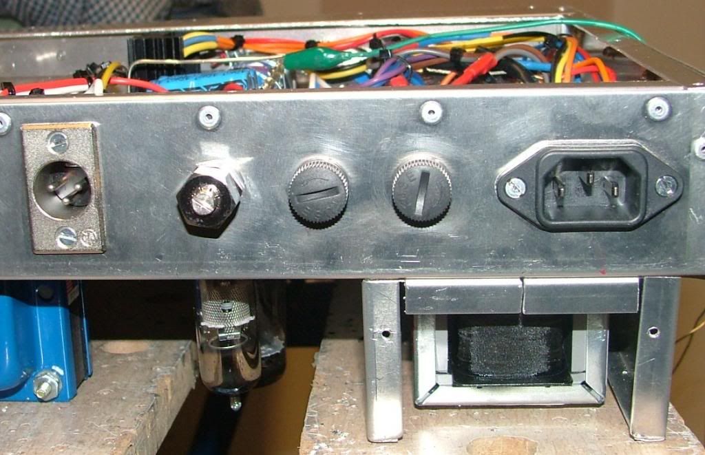
I have fitted the HT adjustment in a handy place on the back panel. Normally the g1 feed should be screened, but the run is so short it wasn't necessary.
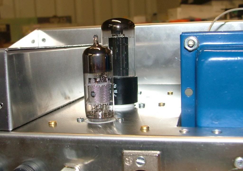
The EF80 and 6W6GT regulator tubes, these are fed from a centre tapped heater supply from a tapping on the B+ bleed resistors.
Found a handy space for the HT adjustment.
The EF80 like the 6084 has a screen which is tied to the cathode/g3.
It all fits in nicely and the voltages check out ok as marked on the revised schematic.
Next job is to make the meter scale and the components on the front panel.
best
DaveP
I think the regulator needs to be fed from the unreg side or it stalls, but in any case I decided to revert to a trusted design.
I decided to redesign the Fairchild regulator for 260V, but using a couple of Zeners instead of the 5651 tube as it takes up more space. I had an EF80 to use instead of the 6084/E80F, it was just a question of changing the operating point to work for 260V.
The Zeners have to have the correct current through them to regulate properly so that sets the feed resistors for the g2 voltage.
Once the cathode voltage is set, you have to work out the values of the control resistor string to get you some adjustment of the g1 voltage below the cathode voltage. The operating point of the pass tube, I'm using a 6W6GT, is going to be several volts below the regulated voltage so its ~255V. The voltage from the B+ supply is ~350V so the plate resistor is dropping 95V. We need high gain so a 220k res gives ~0.5mA plate current. The g2 voltage needs to be ~200V and the Zeners need ~5mA so this gives us a 12k res. The Zener dropper res is 200V - Vk 86V / 5mA which is 22k. Thats how I arrived at the Regulator design,
The heater supply is elevated to 156V to within the spec of the tubes Vk:heater Voltage.
Caps across the Zeners keep it steady and filter hash.
Bypass cap from 260V feeds ripple to grid to cancel.
You have to work out the power rating of all the resistors, so the 22k is 3W and the 12K 7W which are values I had in the box.
I have fitted the HT adjustment in a handy place on the back panel. Normally the g1 feed should be screened, but the run is so short it wasn't necessary.
The EF80 and 6W6GT regulator tubes, these are fed from a centre tapped heater supply from a tapping on the B+ bleed resistors.
Found a handy space for the HT adjustment.
The EF80 like the 6084 has a screen which is tied to the cathode/g3.
It all fits in nicely and the voltages check out ok as marked on the revised schematic.
Next job is to make the meter scale and the components on the front panel.
best
DaveP


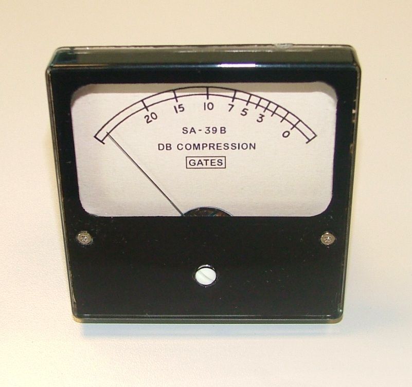
Working on the meter scale.
First, I very carefully removed the existing 1mA scale from the meter.
Next I found the clearest scale from the web images.
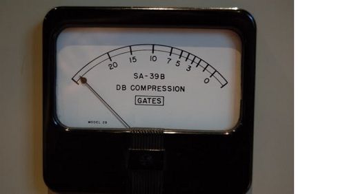
I copied and printed the scale to the correct size to fit the existing scale and cut it out.
Next I stuck the scale on the meter temporarily with pritstick.
I scanned this in and started renovating the scale in MS Paint.
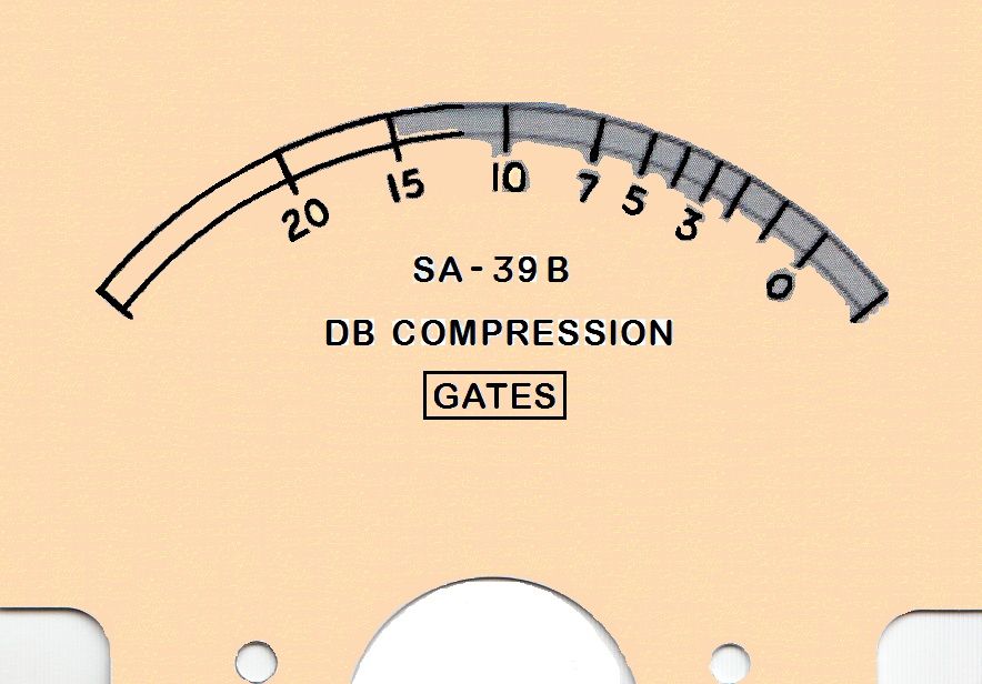
It's a painstaking job to tidy up the scale and offset numbers,(on high magnification) but luckily some windows fonts matched the text. You need to keep the halo of lighter pixels around the text to make it look like natural print. I don't have Photoshop.
The letters are Arial Rounded MT Bold (with the C and O narrowed to suit).
The number 39 is Gungsuh with the drop removed from the 3.
The colour of the scale has to be adjusted to your colour printer, mine has to have a pink tinge to come out cream, if you get it just right on the screen it comes out lime green for me.
As you can see, the scale is still work in progress, but I'll post the finished article next week.
best
DaveP
First, I very carefully removed the existing 1mA scale from the meter.
Next I found the clearest scale from the web images.
I copied and printed the scale to the correct size to fit the existing scale and cut it out.
Next I stuck the scale on the meter temporarily with pritstick.
I scanned this in and started renovating the scale in MS Paint.
It's a painstaking job to tidy up the scale and offset numbers,(on high magnification) but luckily some windows fonts matched the text. You need to keep the halo of lighter pixels around the text to make it look like natural print. I don't have Photoshop.
The letters are Arial Rounded MT Bold (with the C and O narrowed to suit).
The number 39 is Gungsuh with the drop removed from the 3.
The colour of the scale has to be adjusted to your colour printer, mine has to have a pink tinge to come out cream, if you get it just right on the screen it comes out lime green for me.
As you can see, the scale is still work in progress, but I'll post the finished article next week.
best
DaveP
Kingston
Well-known member
DaveP said:I scanned this in and started renovating the scale in MS Paint.
ouch!

You should at least use the free Paint.NET software!
But really these front panel graphics should be done with the proper tools and here's one: http://inkscape.org/
I use corel draw personally, but inkscape is well tooled these days. Two different ways to go about this:
1. import the pixel image to your vector graphics software and redraw the whole thing on top of the original.
2. import the pixel image to your vector graphics software and use "vectorize", "trace" or whatever the vector capture tool is called. And then clean it up.
Beats mucking about with single pixels.
Alan,
I'm putting the scale into a new meter, I don't have an old one, so it will not look exactly like the original meter, but the scale at least will do. I bought a batch of New "Flashstar" meters from CPC/Farnell/ Newark and the scale slips out very easily after you remove two small screws.
Kingston,
I will try this software but you forget how old I am! This stuff does not come easily to me, I don't really understand what you are talking about with your instructions. I used to have Coral Draw in XP but could never really understand how to use all the features. Now I have moved to Windows 7, the Paint program is much improved and fits my level of competence very well!
I'm not actually doing it pixel by pixel just sweeping round on that level.
Thanks
DaveP
Kingston,
I downloaded the Inkscape program (30Meg!)but there is no exe. file so it never even fired up. Completely unuser friendly, they have some work to do on that.
I will stick to Paint as I really hate being frustrated by non-intuitive programs.
best
DaveP
I downloaded the Inkscape program (30Meg!)but there is no exe. file so it never even fired up. Completely unuser friendly, they have some work to do on that.
I will stick to Paint as I really hate being frustrated by non-intuitive programs.
best
DaveP
Kingston
Well-known member
DaveP said:Kingston,
I downloaded the Inkscape program (30Meg!)but there is no exe. file so it never even fired up. Completely unuser friendly, they have some work to do on that.
I will stick to Paint as I really hate being frustrated by non-intuitive programs.
There's a very large selection of installers, unusually so. You might have picked the wrong one. http://inkscape.org/download/?lang=en
http://downloads.sourceforge.net/inkscape/inkscape-0.48.4-1-win32.exe
The point of these vector graphics are that you work with lines and splines (aka curves). You could perfectly trace that curve of the meter and all edits are non-destructive. You can forever keep tweaking the important bits like line/curve width and font type/size. The result is also endlessly scalable since there are no pixels. There are also tutorials, right in the software itself or littered around youtube. The basic use and interface isn't different from paint actually.
Most importantly, the result can be exported directly to someone like frank for CNCing!
Thus endeth thread intrusion.
Kingston
Well-known member
64bit Windows 7 runs all 32bit software perfectly with no performance hit, just like a native 32bit operating system would. It's completely transparent to end user.
Oh well, despite the graphics issues, I managed to finish modding the meter to look like the original.
I have also wired up the Attack, Release and In/out pads but I'll post more pics when the are in the front panel.
best
DaveP

I have also wired up the Attack, Release and In/out pads but I'll post more pics when the are in the front panel.
best
DaveP
Most of front Panel assembled.
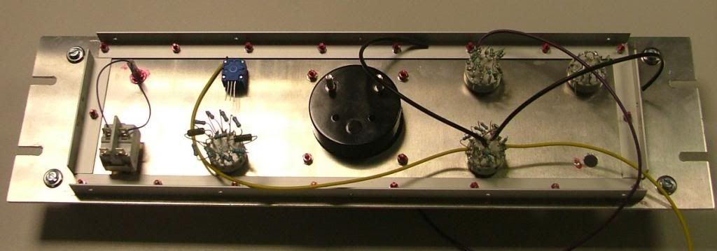
Can't fit the Threshold control as I don't know the resistance values yet, I'll have to find them by experiment when its actually working.
Finished meter in place and control knobs fitted.
The values for the attack and release controls were supplied by Doug Williams at EMRR after he had restored an original for studio use.
I hope it will be finished next week or the week after, then I'll give it a full spec test and run samples of audio before and after.
best
DaveP

Can't fit the Threshold control as I don't know the resistance values yet, I'll have to find them by experiment when its actually working.
Finished meter in place and control knobs fitted.

The values for the attack and release controls were supplied by Doug Williams at EMRR after he had restored an original for studio use.
I hope it will be finished next week or the week after, then I'll give it a full spec test and run samples of audio before and after.
best
DaveP
Kingston
Well-known member
DaveP said:Oh well, despite the graphics issues, I managed to finish modding the meter to look like the original.
That's perfect! The source image was decent resolution and certainly helped.
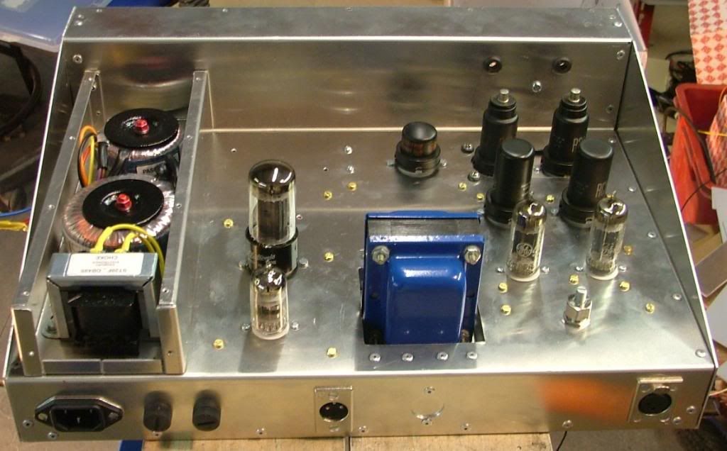
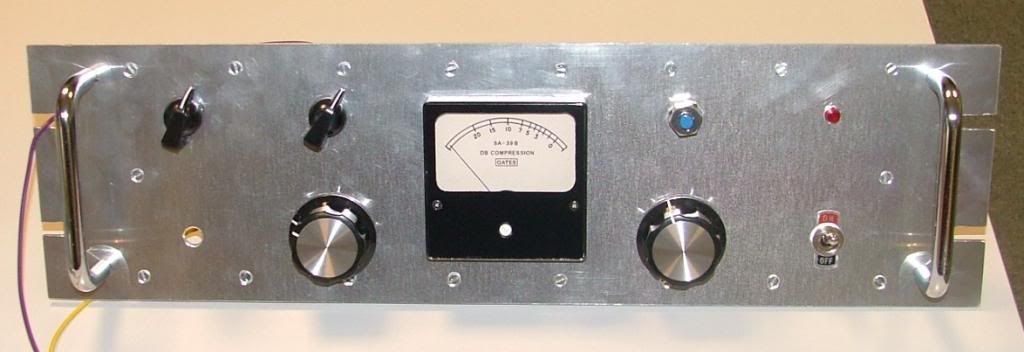
All the wiring for the front and main amp is now done.
Front Panel ready....Always work from schematic and highlight progress.

I will rig up a temporary pot for the threshold to find the correct values for the switch.
Lots of wires to get sorted......
I've now started connecting the two halves and will report next week.
DaveP

Front Panel ready....Always work from schematic and highlight progress.

I will rig up a temporary pot for the threshold to find the correct values for the switch.
Lots of wires to get sorted......

I've now started connecting the two halves and will report next week.
DaveP
Similar threads
- Replies
- 1
- Views
- 770
- Replies
- 1
- Views
- 790