Matador
Well-known member
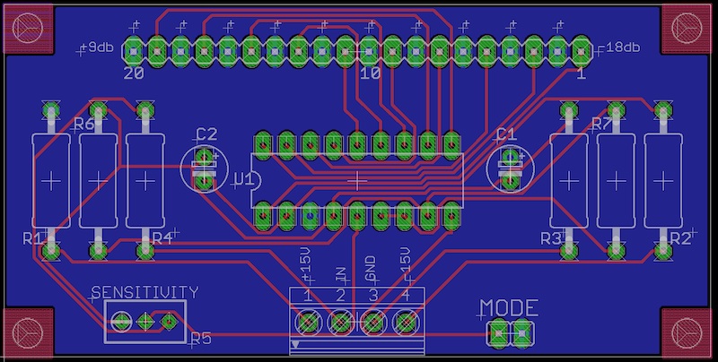
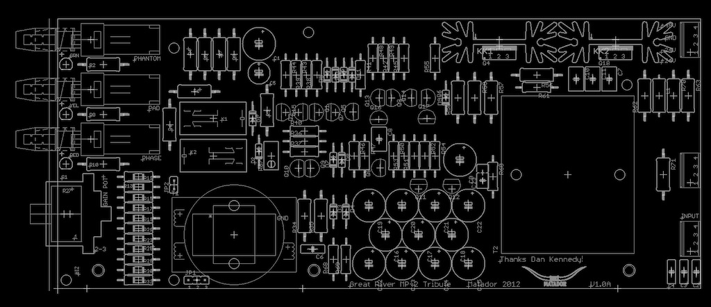
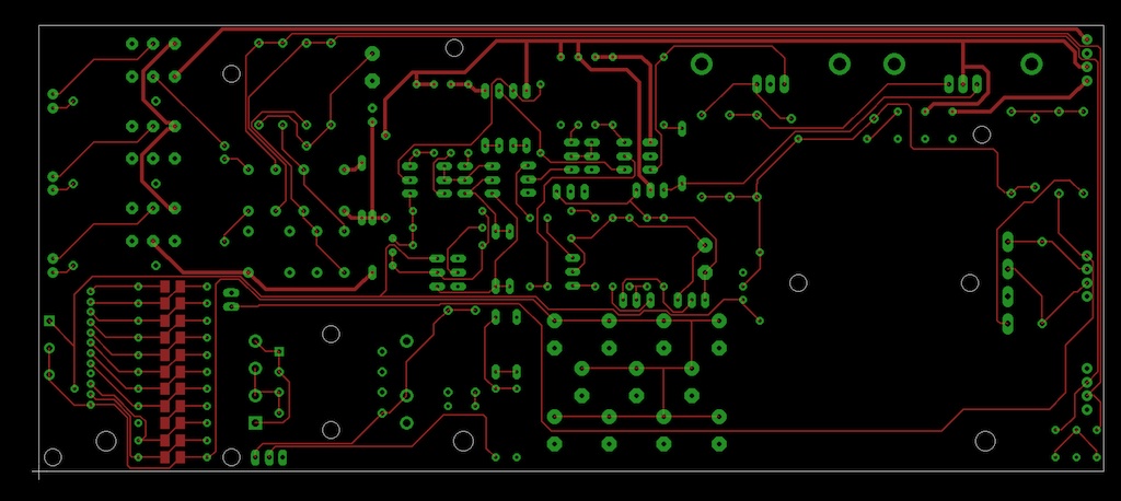
Here are preliminary completed layouts.
Top of PCB:
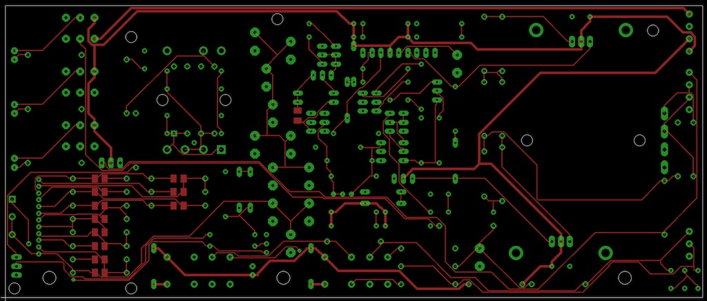
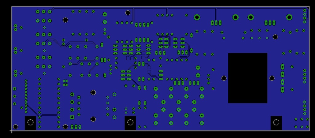
Back of PCB:
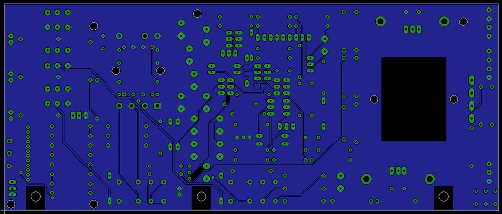
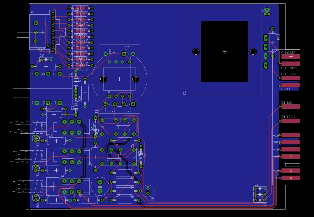
Top of PCB:
Back of PCB:


Ptownkid said:What lead pitch are the connectors?
If there is enough demand (and this board sounds fine and works) I would be happy to copy it to a 51X template. However keep in mind I don't have neither any 51X gear to confirm the design, nor capabilities to make or design front plates so someone else would have to do that.
Ptownkid said:Is it possible to make it 2.54mm?

pachi2007 said:+1 for the 51X layout.
Awesome work Matador!
okgb said:Where the opamp ? although simple , the 1/4" d.i. input does work well , I'd put in at the bottom though
so the cable doesn't dangle over the switches and cover them up . there's an l.e.d. for phantom power ?
3nity said:Matador looks really impressive Tio.
It looks like the board is less congestionned.
Did you thought about a doing a version for Lorlins and not GRayhills??
I mean with a daughter board for lorlin and toggle switches for 48/pad/pol??
This would make the project more affordable and still be quiet fancy.
just my .002 cents.