You are using an out of date browser. It may not display this or other websites correctly.
You should upgrade or use an alternative browser.
You should upgrade or use an alternative browser.
GroupDIY Bridge compressor.
- Thread starter DaveP
- Start date


Help Support GroupDIY Audio Forum:
This site may earn a commission from merchant affiliate
links, including eBay, Amazon, and others.
Hi Erik,
You can for vari-mu types where the current reduces.
A 1mA fsd is fine with a bypass pot to zero it, maybe another resistor as well.
A real VU meter has a diode bridge, a 3.6k series resistor and special ballistic movement.
The meter cost me £3.70 from Ebay plus postage. lovely quality from the 1940's.
best
DaveP
letterbeacon
Well-known member
Lovely stuff Dave!
What do you use for the bus bar? I'm about to put an order in at RS, I'm assuming it's something you got from there...? What gauge is the hook up wire?
Thanks!
What do you use for the bus bar? I'm about to put an order in at RS, I'm assuming it's something you got from there...? What gauge is the hook up wire?
Thanks!
Were the middle supports just separate pieces cut to length and then soldered?
That's it, just pre-bend them first, then pinch them on the busbar so you can solder them.
This is not my idea, most of the amps I used to dismantle in the 60's used that technique. The US seems to go in more for separate turret boards, which lend themselves more to mass production techniques, I guess, one person building boards and another wiring them in.
best
DaveP


letterbeacon said:What do you use for the bus bar?
RS 355-041
The hook up wire I've got in different colours in reels at work, its slightly too thick really but I'm too cheap to buy my own! It's tinned which is most important, never buy untinned hook up wire, its almost impossible to solder when its tarnished after a while.
Typical part number is RS 356-690
best
DaveP
lassoharp said:I've used a common metal clothes hanger before. Just sand the finish off and rebend. Fairly thick though.
Good idea but that would be iron, I think you would really need copper for the low resistance for a ground wouldn't you?.
I'm off to bed now, early start tomorrow.
all the best
Dave
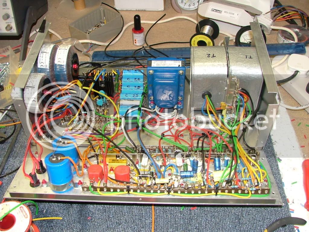
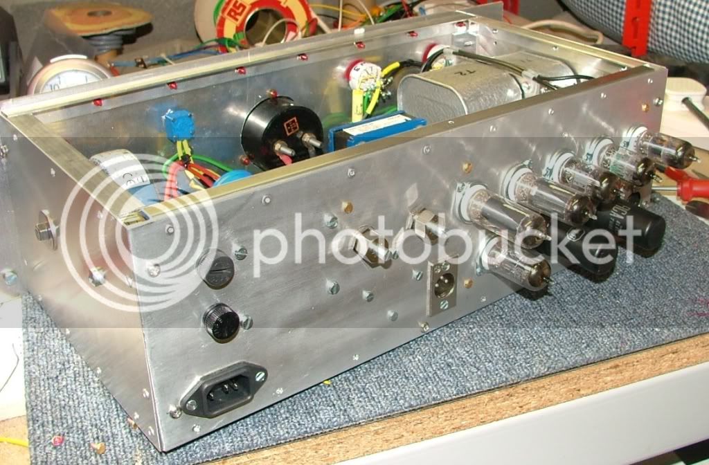
Busy weekend saw most of the components fitted, luckily there is plenty of room in the chassis to fit things neatly. Heat sinks are ready to fit the DC schottky rectifier, and Mosfet regulator.
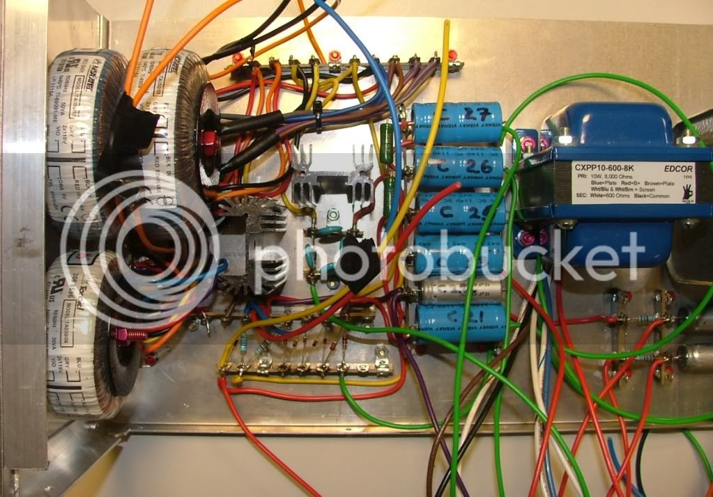
It looks complicated but if you do the heater wiring first then methodically wire one tube at a time, marking a spare schematic as you go, its not as bad as it looks.
All the caps are labelled so EMRR can find his way around in 10 years time!
Pre-wiring the connections makes it easier to connect the back to the chassis later.
Tommorrow I will fit the back and fire up the tubes to check the DC voltage, remembering that the heaters are elevated to 43V
Don't let me forget to rewire it for 115V when it goes stateside!
Later this week I'll finish off the front panel wiring.
best
DaveP
ruairioflaherty
Well-known member
Outstanding Dave, loving the build.
strangeandbouncy
Well-known member
Such precise, neat wiring . . . . sigh . . .
take note, Guys n' Gals!
this is how it should be done!
take note, Guys n' Gals!
this is how it should be done!
strangeandbouncy said:Such precise, neat wiringSeveral people have said that, but I'm only doing my best to copy how it used to be done. In fact I don't think I come up to the mark compared to what I've seen in the past. I guess this method of electronic construction is just of historical interest now, but I promise you I will never do a SMA (Stupid Microscopic Artifacts) project.
rant over
best
DaveP
rafafredd
Well-known member
Yes! Best PtoP ever!
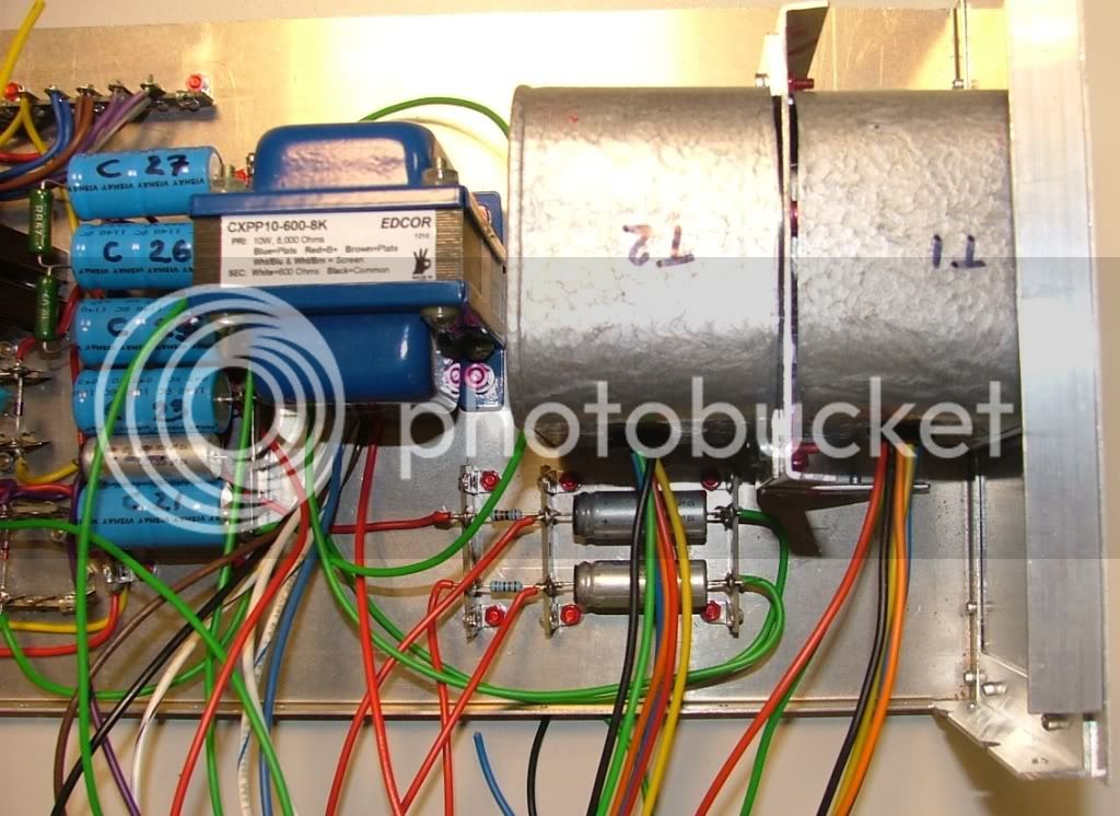
I love the idea of using sawed off coffee cans for transformer screens. I'm going to have to steal that, if you don't mind.
Joe
Joe
joe-electro said:I love the idea of using sawed off coffee cans for transformer screens. I'm going to have to steal that, if you don't mind.
Joe
Enough to change brands to get the cans? ;D
Its French "Illy" coffee beans. :
")
DaveP
Almost there now....
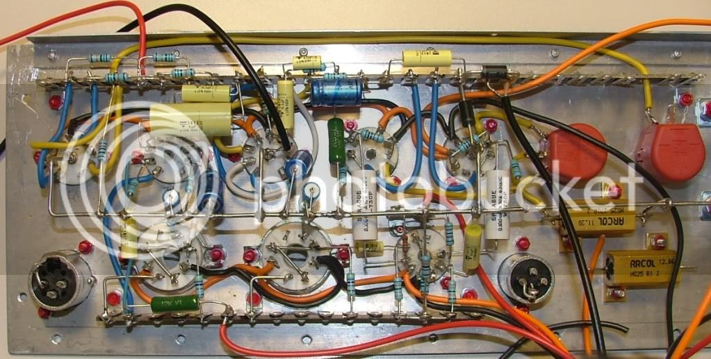
The back panel is finished and wired in. Labelled screened cables will connect to the front panel.
The front panel has all its components in place, the dB meter is secured with brass screws and nuts to avoid magnetic interference.
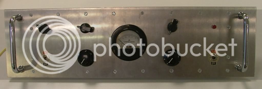
From top left to right...Attack, Release, Threshold & Neon.
Bottom left to right...Comp in/out, Input level, Output level & Power on off.
The back of the front panel ready to wire.
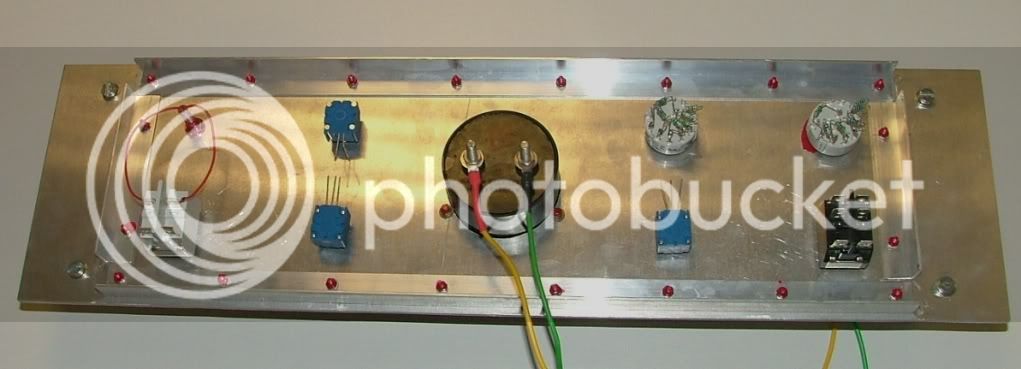
All the pots are conductive plastic types for low noise.
I hope to finish it next week and test the specs.
best
DaveP
The back panel is finished and wired in. Labelled screened cables will connect to the front panel.
The front panel has all its components in place, the dB meter is secured with brass screws and nuts to avoid magnetic interference.
From top left to right...Attack, Release, Threshold & Neon.
Bottom left to right...Comp in/out, Input level, Output level & Power on off.
The back of the front panel ready to wire.
All the pots are conductive plastic types for low noise.
I hope to finish it next week and test the specs.
best
DaveP
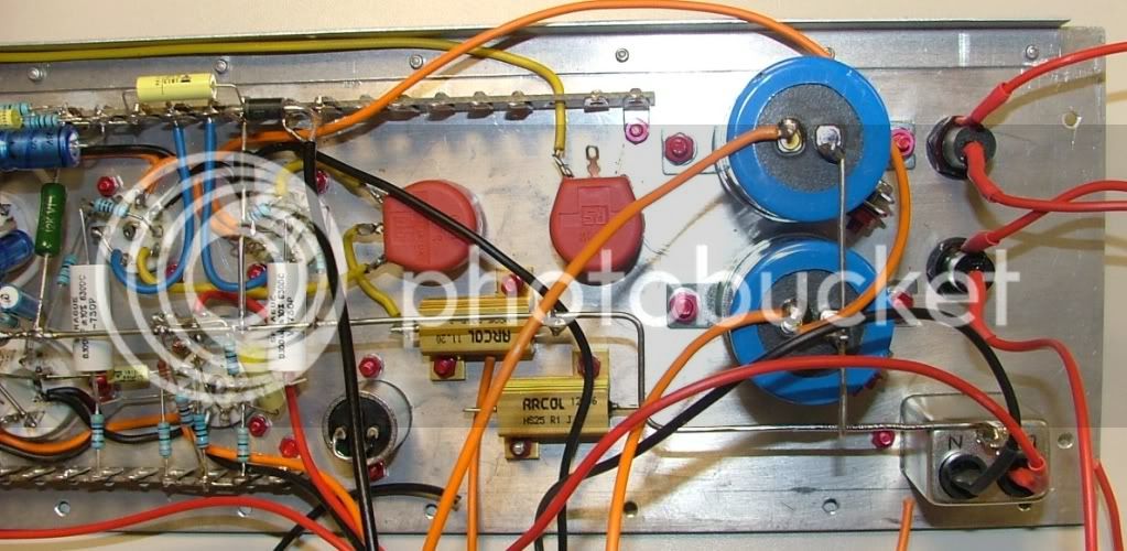
Finished wiring in all the components tonight.
The front panel wiring
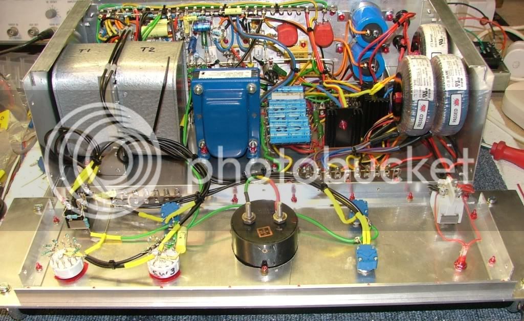
All the tubes in ready for lighting up.
I only put the fuse in for the heater supply to start with, everything worked ok but voltage was too high so turned off and added more resistance between the smoothing caps. Turns out this supply needs 1.18 ohms, so will have to fit a 0.18 ohm plus the 1 ohm already there. I'll have to drill 2 new holes but it can wait till tomorrow now....
Only job left to do is cut out and fit the top cover, that will be done lunchtime.
I'll fire up the HT with a fresh brain and quicker reactions tomorrow!
best
DaveP
The front panel wiring
All the tubes in ready for lighting up.
I only put the fuse in for the heater supply to start with, everything worked ok but voltage was too high so turned off and added more resistance between the smoothing caps. Turns out this supply needs 1.18 ohms, so will have to fit a 0.18 ohm plus the 1 ohm already there. I'll have to drill 2 new holes but it can wait till tomorrow now....
Only job left to do is cut out and fit the top cover, that will be done lunchtime.
I'll fire up the HT with a fresh brain and quicker reactions tomorrow!
best
DaveP
Similar threads
- Replies
- 98
- Views
- 15K
- Replies
- 575
- Views
- 100K
- Replies
- 32
- Views
- 10K
Latest posts
-
 LDC and SDC (nominally cardioid) polar patterns varying by frequency
- Latest: Det van Rijn
-

-

-
-

-

-
-
