letterbeacon
Well-known member
Haha! The coffee can as a shield is a great idea!


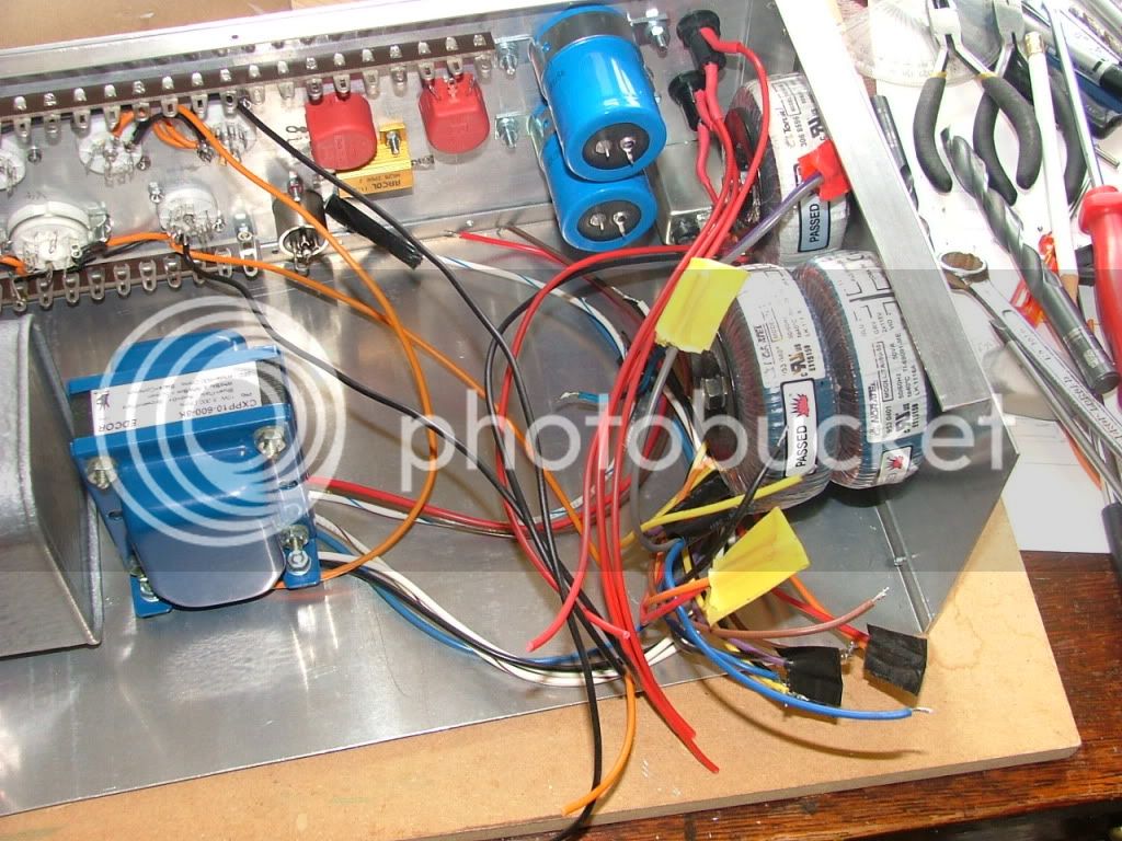
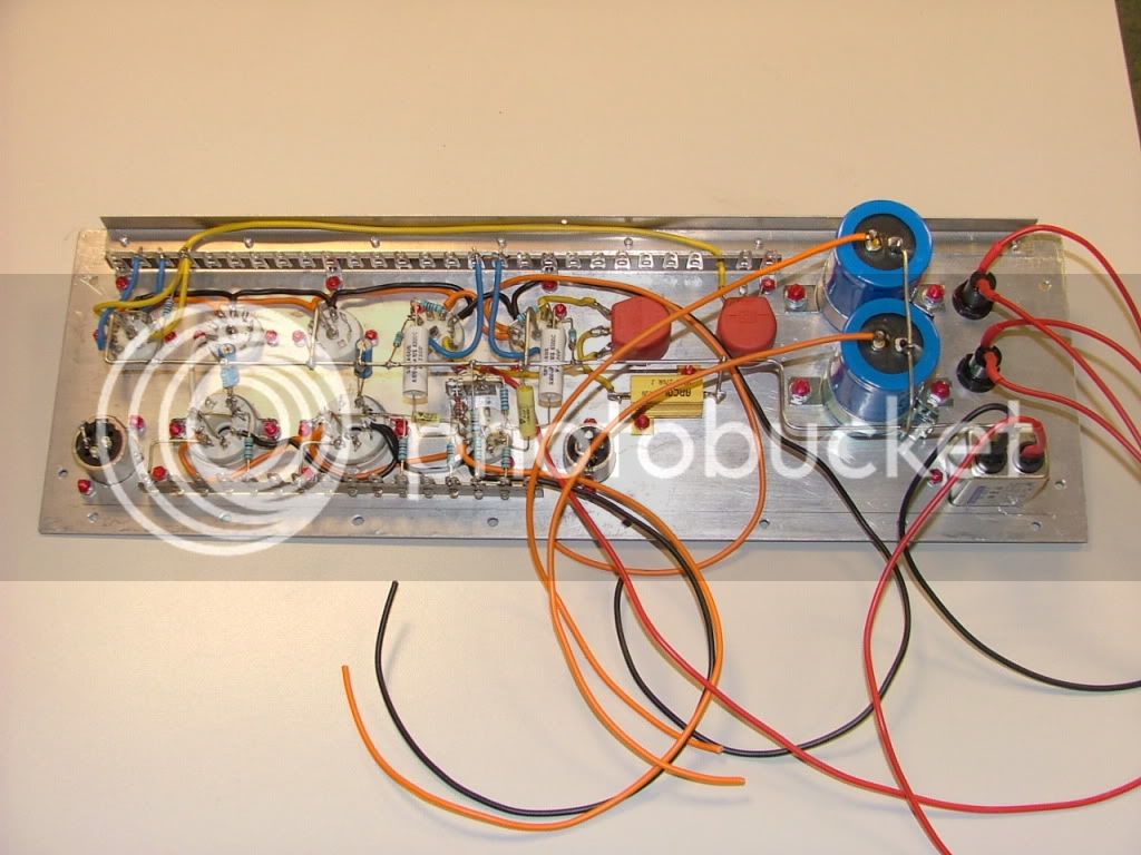
") But the transformers not yet fitted, I forgot to take home some grommets for the wiring, have to finish the sub assemby during the week.
But the transformers not yet fitted, I forgot to take home some grommets for the wiring, have to finish the sub assemby during the week.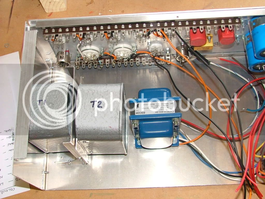 (is that right written?)