GSSL add-on help thread

GroupDIY Audio Forum

Help Support GroupDIY Audio Forum:

This site may earn a commission from merchant affiliate links, including eBay, Amazon, and others.
Well i resoldered the wires the from MAIN to SSC PCB and now so far the unit ssems to work  ::) :-X

No cracking, and both sides compress the same, also the presets (60-200) do their job - i still have to adjust TM TL.

I think the description confused me a bit (see attached images):


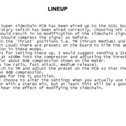
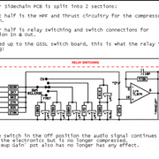
...With the switch in the "OFF" Position the signal continues to go through the electronics but is no longer compressed... make up gain no effect... The In/Compression switch is ment and not the rotary - i thought it should be the side chain rotary  ::)  shame on me  :mad:

Thank you a lot Script... i will go for TM TL now and than check the LEDs
 
Good to hear you have sound  8) BTW, that was my break.

If I remember correctly, I adjusted the TM and TL filters not using vague compression deflection on the meter (are they calibrated correctly?) but instead used a 1KHz signal and adjusted them to the same AC output reading on the SSC board output (pre- or post-47K) as in the "OFF" bypass position. But there was something with it that didn't work the way I wanted it to. --//--Looking at my scribbles it seems it was the 1K resistor plus 10K trim giving only 11K max in the inverting opamp feedback loop, while ideally, in my books, it should be +/-12K. (same as input of SSC board and  !!same as when SSC board is not installed!!). So I changed that 1K for something higher such as 6K8 (or whatever gives more than 12K togehter with the 10K trim). I think I did the same with the TM and TL resistors in the feedback loop.. -- I'm not saying though that you have to do it that way. And desoldering anything on those boards can be borderline.
 

Attachments

  • SSC board_trimmer in feedback loop.jpg
    SSC board_trimmer in feedback loop.jpg
    43.7 KB · Views: 32
Script said:
Good to hear you have sound  8) BTW, that was my break.

If I remember correctly, I adjusted the TM and TL filters not using vague compression deflection on the meter (are they calibrated correctly?) but instead used a 1KHz signal and adjusted them to the same AC output reading on the SSC board output (pre- or post-47K) as in the "OFF" bypass position. But there was something with it that didn't work the way I wanted it to. --//--Looking at my scribbles it seems it was the 1K resistor plus 10K trim giving only 11K max in the inverting opamp feedback loop, while ideally, in my books, it should be +/-12K. (same as input of SSC board and  !!same as when SSC board is not installed!!). So I changed that 1K for something higher such as 6K8 (or whatever gives more than 12K togehter with the 10K trim). I think I did the same with the TM and TL resistors in the feedback loop.. -- I'm not saying though that you have to do it that way. And desoldering anything on those boards can be borderline.

Yeah i did a break too - seems to work :-X

i didn't calibrate the meter....

... i tried to adjust TM and TL with a 1 Khz signal with 4db output to 8db compression like in the description but i don't get any change when i adjust the trimmers...

maybe im doing it wrong (like everything else ;D) ?! Im using ableton... I put the 1 Khz audio file on an audio track an set the track volume to 4db. Im routing audio through the compressor with the external effect utility.
With sidechain off i adjust the threshold to 8db compression - with sidechain on TM the compression goes to maybe 6-7db and no change when i turning the trimmer - at TL the compression goes to 0 and when i turn threshold all the way down to to -15 the compression goes to maybe 0,5db.... also no change when turning the trimmer...

could it be that ive blown the ne5532?... it feels like there is still no difference when i plug them out

The output level is uneven L/R and so i was thinking about to modify the THAT circuits related to http://diy.fischerworks.com/gssl_vca.shtml as my 2180B VCAs are pretrimmed

by the way i got the LEDs working without any additional resistors  :eek:
 
Let there be sound, let there be light  8)

Im routing audio through the compressor with the external effect utility.
?? The EXT IN is a setting by itself. and is not affected by the other filter settings. Feed your 1KHz signal into the comp's L and R inputs. You do this, right ?

Fried IC : You could swap the two NE5532s in the filters. One IC is for the active TM and TL filters, the other is the boards input and output buffers. Swap the ICs and go thru all settings as before. If the problem is absolutely the same, your ICs are fine and the problem is elsewhere.

Alternatively, you could measure AC at the IC output pins. Search for image of "NE5532 pinout" (it's pins 1 and 7). As before, feed your 1KHz signal into the comp's L and R audio inputs, set multimetre to AC, negative probe aligator-clipped to starground and positive probe to IC output pin..Do you get any reading at all ? Then change output volume in Ableton. Do the readings change accordingly ?

Calibrating the TM and TL : I claim it's impossible to set the filters correctly by eye (via VU meter) or by ear. Measure at board output 47K while switching thru the filter settings (skip the EXT IN). As a starting point, with a clean 1KHz signal, they should all read fairly the same. If not, adjust trimmers until they do. Then listen to the TM and TL filters at work, compare to 'OFF'. Could slightly adjust filter trim to 'liking', but have to remember that louder always sounds better.

P.S.: The VCA trimmers have to do with distortion at very low levels, not overall volume. You do use the exact same VCA type L and R, no ?
 
Script said:
Let there be sound, let there be light  8)
?? The EXT IN is a setting by itself. and is not affected by the other filter settings. Feed your 1KHz signal into the comp's L and R inputs. You do this, right ?

Fried IC : You could swap the two NE5532s in the filters. One IC is for the active TM and TL filters, the other is the boards input and output buffers. Swap the ICs and go thru all settings as before. If the problem is absolutely the same, your ICs are fine and the problem is elsewhere.

Alternatively, you could measure AC at the IC output pins. Search for image of "NE5532 pinout" (it's pins 1 and 7). As before, feed your 1KHz signal into the comp's L and R audio inputs, set multimetre to AC, negative probe aligator-clipped to starground and positive probe to IC output pin..Do you get any reading at all ? Then change output volume in Ableton. Do the readings change accordingly ?

Calibrating the TM and TL : I claim it's impossible to set the filters correctly by eye (via VU meter) or by ear. Measure at board output 47K while switching thru the filter settings (skip the EXT IN). As a starting point, with a clean 1KHz signal, they should all read fairly the same. If not, adjust trimmers until they do. Then listen to the TM and TL filters at work, compare to 'OFF'. Could slightly adjust filter trim to 'liking', but have to remember that louder always sounds better.

P.S.: The VCA trimmers have to do with distortion at very low levels, not overall volume. You do use the exact same VCA type L and R, no ?

The external effect ultillity is an Ableton Plug for routing external effects - i send the audio to the ins of the compressor and its catched at output - no external sidechain connection...

The VCAs are all 3 the same (2180B)

I gonna test switching and measuring ICs (but they've already been switched by accident), i also got a spare one...

Let there be sound and light!!!!!

Thank you!!!!
 
Hi Guys. I hope someone of you can help me. I built a GSSL with two SuperSidechains (PCB grinder) and a turbo board (ExpatAudio), but it doesn't work yet. Without the modifications, the compressor works perfectly. After I installed the modifications and nothing worked, I sent the compressor to Markus Samper (greetings go out). He said that the two side chains and the turbo board were working properly, but he didn't have time to check the cabling and said that the fault must be in the cabling. For the cabling, I used the Don-Audio sketch (https://www.don-audio.com/GSSL-Turbo-Sidechain-Wiring) because I have the same equipment (British push buttons etc.). The left push button (compressor) should be the bypass button, so when pressed, the button lights up and the compressor works. The right push button switches the turbo mode on when the button is pressed. Furthermore, I once read in an older post here in the forum that only one relay has to be installed on the SideChainBoards for this circuit. Is that true because I installed the relay on each SC-board???? Here are two more sketches of my current wiring. I hope someone can help me. Best regards: Fritz
 

Attachments

  • Cabling GSSL+2SSC+Turbo - Part 1 (1).jpg
    Cabling GSSL+2SSC+Turbo - Part 1 (1).jpg
    845.3 KB · Views: 30
What exactly doesn't work ?
You have a multimeter ?
Check for connectivity between the boards to the pins of your switches and from there to the destination boards. Do the switches route everything to where it should go ? Unit doesn't need to be / is actually better turned off for this.

Added:  Is your switch for engaging Turbo a DPDT type ?
Your image does not show wiring of the Turbo ratios. You need a 2x3 rotary for this.
 
Hi Script! Sorry for the late reply.
Script said:
What exactly doesn't work ?
I cant say that exactly because first i want to be sure that my two sketches to be correct before i turn on the compressor.
Script said:
You have a multimeter ?
yes
Script said:
Do the switches route everything to where it should go ?
That is the question. Various sketches and possibilities for this combination are circulating in the forum. I would be interested to know if there are any mistakes in my sketches. I am particularly interested in whether the connections "Com-Off-On-PotA-Pot B" and the section "To In SW - Ret - +/- In LED" are correctly connected. What is the difference between the return point on the left side of the SSC board and the right side (under "To in SW")?

Script said:
Added:  Is your switch for engaging Turbo a DPDT type ?
As far as I know, yes. Exactly those are shown on the sketch.

Script said:
Your image does not show wiring of the Turbo ratios. You need a 2x3 rotary for this.
In the second part of the sketch I just made only a note about this. the turbo ratios are linked in exactly the same way as in the expat's manual.
Thank you for your interest
 
But you know that it doesn't work. Well, then I'd first use the meter and set to signal generator (maybe a little speaker symbol on yours) to check connectivity of all wires. I'd focus first on the Turbo switch. Could be as simple as two wrongly hooked up wires there. As for how the bypass switch should connect, simply read back a handful of posts in this very thread.
 
What is the difference between the return point on the left side of the SSC board and the right side (under "To in SW")?
Ah, yes, they are somewhat unfortunately named. The SSC board is two independent circuits : the entire filter with connections on the left  plus  the IN/OUT switch with LED and relay on the right. So 'Return' on left side of board is the output of the filter with audio running through it. The 'Return' on the right side of the board is for connecting the compressor IN/OUT switch ('IN SW') with power running through it.
 
Script said:
Well, then I'd first use the meter and set to signal generator (maybe a little speaker symbol on yours) to check connectivity of all wires.
checked everything multiple times with the multi signal generator.
Script said:
Could be as simple as two wrongly hooked up wires there. As for how the bypass switch should connect, simply read back a handful of posts in this very thread.
So if I understand correctly are 2 connections on the turbo switch wrong? I have read all the posts in this thread, but I haven't really gotten any smarter, on the contrary, now I'm even more confused. Maybe you can tell me which post numbers I should take a closer look at.
Script said:
Ah, yes, they are somewhat unfortunately named. The SSC board is two independent circuits : the entire filter with connections on the left  plus  the IN/OUT switch with LED and relay on the right. So 'Return' on left side of board is the output of the filter with audio running through it. The 'Return' on the right side of the board is for connecting the compressor IN/OUT switch ('IN SW') with power running through it.
This means that the two "Out" points of the SSC boards in the Don Audio sketch (https://www.don-audio.com/GSSL-Turbo-Sidechain-Wiring) corresponds to the returns on the right side of my SSC- Boards?
 
There were several different SSC boards available over time. I was referring to the ones by PCBgrinder. The SSC boards shown in that link to DonA must refer to a different board. On the PCBgrinder SSC boards, the audio out of the filter is definitely on the left side of the board. Can you upload a picture of your boards ?
 
Script said:
There were several different SSC boards available over time. I was referring to the ones by PCBgrinder. The SSC boards shown in that link to DonA must refer to a different board. On the PCBgrinder SSC boards, the audio out of the filter is definitely on the left side of the board.
I almost thought that the SSC boards in the don audio sketch are different from the ones on the pcb grinder
Script said:
Can you upload a picture of your boards?
I have the same SSC boards as in the sketches, i.e. those from the pcbgrinder
 
Are your switches maybe tilted by 90 degrees ? Did you check for connectivity between boards, that is whether everything is routed correctly through the switches from origin to destination) ? I am starting to guess here.

Or, if you used IC sockets, you can always pull out the ICs and turn the unit on safely. Do your push buttons light up correctly and does the relay switch with a click ?
 
Script said:
Are your switches maybe tilted by 90 degrees ? Did you check for connectivity between boards, that is whether everything is routed correctly through the switches from origin to destination) ? I am starting to guess here.

Or, if you used IC sockets, you can always pull out the ICs and turn the unit on safely. Do your push buttons light up correctly and does the relay switch with a click ?
ok, yesterday I checked all connections again and turned on the compressor and ran sound through. At the beginning I had the same problem as before when I sent the compressor to M. Samper. But I found the problem. The connection "+/- In LED" on the right side of the first SSC board with the compressor button is completely superfluous and does not serve any purpose. After I disconnected the connection (+/- In LED) everything worked perfectly. Anyway, so far it makes the impression. The push buttons light up when they should, the relays click, less compression when I switch up the SC filter and when I switch on the turbo mod, it compresses about 5 db less, but the side signals are audibly stronger. In my opinion, he is now doing exactly what he should be doing. It would be interesting if a professional could watch and listen to the whole thing again, but I think that's okay. Maybe I'll send him back to Samper for a check if he has a little more time. In the appendix again the correct circuit diagram (without the "+/- In LED" connection). Best regards and thanks again for your tips script.
 

Attachments

  • Cabling GSSL+SSC+Turbo - Part 1.jpg
    Cabling GSSL+SSC+Turbo - Part 1.jpg
    829.3 KB · Views: 28
TimKR said:
The external effect ultillity is an Ableton Plug for routing external effects - i send the audio to the ins of the compressor and its catched at output - no external sidechain connection...

The VCAs are all 3 the same (2180B)

I gonna test switching and measuring ICs (but they've already been switched by accident), i also got a spare one...

Let there be sound and light!!!!!

Thank you!!!!

Back again after beeing on night shift for 5 nights...

The ICs are working correct...

I worked out that the ext. SC position is at the right side under TL (i thought it is left under off)  looking at the front of the device... so off, ext and 60 - 200 settings are working.  :eek: :p

How do i set up the measuring at the output 47K for TL TM adjust and which 47K do you mean?

Thanks Script
 
fritz said:
ok, yesterday I checked all connections again
Seems like you have a working unit :) How to calibrate the SSC filters with the trimmers is described above in this very thread twice. You might want to give it a try. It's really not that difficult.
---
5dB (actually 6dB on paper) build-up of sidechain signal in 'Aarhus' mode (not in 'Turbo' mode) is due to sidechain signals simply being mono'ed after leaving the filter boards. This makes the sidechain signal louder and therefore makes the unit compress more (by said 6dB). This is kind of 'normal' for Aarhus mode and observed by many builders, but it makes it impossible to directly A/B with Turbo modes, which is a real nuissance.

FIX: A possible 'fix' is at the audio input resistors to the SSC board. The how-to is actually described above, but worded differently: Those on-board input resistors want to be 10K on both boards for 'Turbo' mode, but on-board 20K on each board for 'Aarhus' mode to compensate for mono-build-up. With 20Ks at the inputs the signals are attenuated down before entering the filters, so that the mono-build-up at the '47K juntion' on the main board yields a signal loudness comparable to Turbo mode. Only then is it possible to A/B the modes at 'equal' compression amounts and really hear at the flip of a switch what the two modes really do.

HINT: (1) you have an unused relay on the second SSC filter board that could maybe be hacked to flip two signals. (2) The PCBgrinder boards come with TWO audio inputs per board for 'L' & 'R' channel signals, which are then mono'ed on-board before entering the filter section, but with two SSCfilter boards ONLY ONE input each is used. On your sketch, you use the L inputs with dark blue and light blue wires. (3) You have DC on your Turbo frontpanel switch.

I do not know the switches that you are using (you have to figure IN that out yourself), but trying to make them activate that extra relay might be worth the effort. Then that relay could be used to either (A) route the sidechain audio IN signal to either a 10K input or 20K input on the SSC board for the two modes, or (B) place a 20K resistor in parallel to an on-board 20K resistor (20K | 20K = 10K). Solution B is how I did it.
---

With turbo and 2xSSC filter boards you have opted to DIY a highly complex unit. You have made it this far and you are almost there... ;)
 
TimKR said:
I worked out that the ext. SC position
Rewiring the rotary --and it can be wherever you want

TimKR said:
How do i set up the measuring at the output 47K for TL TM adjust and which 47K do you mean?
There is only one 47K on the SSC filter board. Ah, yeah, no schematic, dough. And silkscreen unreadable with components in place, double-dough -- Probe at filter board audio output where the wire leaves the board should do it. (Neg. probe to starground ;) )

TimKR said:
night shift for 5 nights
Otsukaresama.
 
Script said:
Rewiring the rotary --and it can be wherever you want
There is only one 47K on the SSC filter board. Ah, yeah, no schematic, dough. And silkscreen unreadable with components in place, double-dough -- Probe at filter board audio output where the wire leaves the board should do it. (Neg. probe to starground ;) )
Otsukaresama.

Otsukaresama - definitly....  8)

Which mode on multimeter? AC?

I attached the SSC Board in good resolution... There is one 47K for OFF and one going to return...


Latest posts

Back
Top