GSSL HELP THREAD!!!

GroupDIY Audio Forum

Help Support GroupDIY Audio Forum:

This site may earn a commission from merchant affiliate links, including eBay, Amazon, and others.
Nice, I love this diagram!  for a newbie it's nice and easy to read ;)
Nanitlig said " A SPDT will work for mono sidechain or a DPDT if you want to switch an LED also on the other half of the switch" - but your diagram shows a DPDT..  what's best/correct?  I don't want an LED..
The circuit rejoins the 47k resistors on the same side that it splits from?
Sorry about the questions, I promise I'll stop asking before christmas day!  :)


Harpo said:
wthrelfall said:
would you be able to post a picture similiar to Nanitlig's one showing your method?
Something like this.
Now compare this with the schematic snipplet from some post above and how this matches your pcb when following the parts and traces, so you can do this yourself in the future.
 
wthrelfall said:
Nice, I love this diagram!  for a newbie it's nice and easy to read ;)
This will not always be paint_by_numbers.com here. Did you already try to read the schematic and identify the parts in question?
Nanitlig said " A SPDT will work for mono sidechain or a DPDT if you want to switch an LED also on the other half of the switch" - but your diagram shows a DPDT..  what's best/correct?  I don't want an LED..
You'd need double the cap value with a single cap when inserting in the summing node (Nanitligs version, right side of both 47K summing resistors). This cap needs to be replaced with two half this value caps for same response when you upgrade to a 'turbo' circuit (separate sidechain VCA per L/R channel) and this will require a dual pole switch to keep channels separate.
The circuit rejoins the 47k resistors on the same side that it splits from?
Instead of only a resistor you now have a series string of cap followed by resistor. Shorting out the cap with your switch disables the HPF function and only the resistor stays in circuit. Nanitligs version does the same, but after summation for GSSL mode only. Just have a look at the drawings schematic/silkscreen.
 
OK, I think I understand, and yes, i'll study the schematic!
really appreciate your help.


Harpo said:
wthrelfall said:
Nice, I love this diagram!  for a newbie it's nice and easy to read ;)
This will not always be paint_by_numbers.com here. Did you already try to read the schematic and identify the parts in question?
Nanitlig said " A SPDT will work for mono sidechain or a DPDT if you want to switch an LED also on the other half of the switch" - but your diagram shows a DPDT..  what's best/correct?  I don't want an LED..
You'd need double the cap value with a single cap when inserting in the summing node (Nanitligs version, right side of both 47K summing resistors). This cap needs to be replaced with two half this value caps for same response when you upgrade to a 'turbo' circuit (separate sidechain VCA per L/R channel) and this will require a dual pole switch to keep channels separate.
The circuit rejoins the 47k resistors on the same side that it splits from?
Instead of only a resistor you now have a series string of cap followed by resistor. Shorting out the cap with your switch disables the HPF function and only the resistor stays in circuit. Nanitligs version does the same, but after summation for GSSL mode only. Just have a look at the drawings schematic/silkscreen.
 
??? I'm curious.  With the HPF to the right of the summing resistors, then wouldn't the 15k (with the 100pF removed and a jumper to ground) be the resisting element following the capacitor creating the filter?  1/(6.28*15000*47E-9)=225Hz.  And I thought phase angle for HPF was +45°.  But placing the caps before the 47k would make those resistors part of the resisting element of the filter?  I've already wired in my relays for turbo and HPF after the 47k, as the turbo install manual suggests.  I put in two DPDT relays.  One to switch from (off) summing or (on) splitting at the next relay.  The second relay in turn bypasses both L/R HPF caps (off) or engages them (on) to each detector.

48210-231211134741.gif
 
Nanitlig said:
??? I'm curious.  With the HPF to the right of the summing resistors, ...
The summing resistors are the resistive element of this HPF. This is a series string connection. You can exchange the R and C element, giving the same result. These connect to a virtual ground node with the current-in current-out VCA in between. Taking the VCA out and link VCA socket pins1/8 should make it even more obvious, and doing so, just keep in mind the VCA itself is inverting, so after current-to-voltage conversion in the VCA following opamp, signal phase will be 180° off. 
...then wouldn't the 15k (with the 100pF removed and a jumper to ground) be the resisting element following the capacitor creating the filter? to 1/(6.28*15000*47E-9)=225Hz. 
The 15K is NOT part of this HPF, as repeatadly said.
You said, you already built it, so it would be easy to prove by decreasing this 15K to maybe 7K5 (just croko-clip another 15K in parallel). By your assumtion, cutoff frequency then would rise to 450Hz. A quick simulation instead shows, the corner frequency of this HPF doesn't move a single Hz, but try it yourself.
And I thought phase angle for HPF was +45°.
AFAIK its -ARCTAN(cutoff_frequency/test_frequency)*180/PI(). Both frequencies the same, where cutoff_frequency is -3dB down or amplitude response is 1/SQRT(2), phase response is -45°.
But placing the caps before the 47k would make those resistors part of the resisting element of the filter?
There is no other resistive element. Same value caps in front of each 47K summing resistor, cutoff freq. is 1/(6.283*47000*C); single cap after junction of both summing resistors, cutoff freq. is 1/(6.283*(47000/2)*C).
 
hey Guyz,

i'm new here, and i hope u can help me solving a strange error in my ssl.
after reading a lot of thread's if noticed that i had a ref7 board from audio kitchen, and some of the resistors were not the right value.

but i stil have this error:
when i put signal trough my gssl, its sounds ok. but when I try to hit the compressor (bring the treshold down). it is compressing but there is a kind of bumpy klapping distortion going on.
ratio 2 is not working, 4 and 10 are working, release is working fine, makeupgain is also OK. But when compressing, al the setting gives me that weird distorted compression.
is there more info u guyz need to get my problem clear? pleas sayso.

Thanx a lot!
Bram
 
fishboon89 said:
hey Guyz,

i'm new here, and i hope u can help me solving a strange error in my ssl.
after reading a lot of thread's if noticed that i had a ref7 board from audio kitchen, and some of the resistors were not the right value.

but i stil have this error:
when i put signal trough my gssl, its sounds ok. but when I try to hit the compressor (bring the treshold down). it is compressing but there is a kind of bumpy klapping distortion going on.
ratio 2 is not working, 4 and 10 are working, release is working fine, makeupgain is also OK. But when compressing, al the setting gives me that weird distorted compression.
is there more info u guyz need to get my problem clear? pleas sayso.

Thanx a lot!
Bram

maybe somewhere around ctrl pcb u forgot to solder something? i had distortion coming from my release switch .. seemed i didnt solder the pole hehe :D go figure! late night soldering

i hope u find the basterd soon!
 
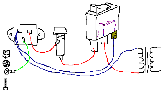
Would anyone be able to advise me on how to wire a DPST illuminated power switch to my GSSL..  looks like this one with 4 connections http://www.partsconnexion.com/media/product/controls/SWITCH-70154.jpg
Thanks.
 
wthrelfall said:
Would anyone be able to advise me on how to wire a DPST illuminated power switch to my GSSL..  looks like this one with 4 connections http://www.partsconnexion.com/media/product/controls/SWITCH-70154.jpg
Thanks.
it looks from that angle like SPST with only 2 legs there no?
anyways.. if it has a third leg maybe is like something once harpo told me

mains_hookup.gif


happy switchin on!

EDIT : damn harpo that was fast! :D merry christmas altho late! and happy new year for u man!
 
Got a problem with my build,

first of all, i had the tl074 reversed in the socket, replaced it with a new one (just in case it got burned or something), but the problem persists: no compression

sound goes thru, make up gain works, panel backlight works, bypass works, gain reduction meter doesn't move, threshold and all other controls don't respond.

checked all connections/diodes/caps polarity/links

any suggestions on proceeding?
 
synnys said:
first of all, i had the tl074 reversed in the socket, replaced it with a new one (just in case it got burned or something)
If it was powered while reversed in the socket, expect the chip to be blown.

.. bypass works, gain reduction meter doesn't move ..
both parts of the bypass switch ?
1mA fsd meter in series with a fixed ~2K resistor or a 4K7 rheostat with initial value about centered ?
 
Hi Guys,

'Hope you can help me out.
I have the turbomod with identical parts as the mainboard (and 2181VCA's).

After some testing I found that in turbomode putting signal on only the left input (=the turbo SC), compression is 6dB less than when putting signal on only the right channel.
SSL-mode is working fine.

(Also switching ratio higher, gives lower readout on the meter with left only input, while with right input only, increasing ratio also increases meter reading)

Swapping VCA's gave the same result -> left giving less compression.

Measuring all resistors and diodes gave the following weird "problem":
All 3 of the 20k resistors in the detector measure 14k on the turbo, while on the mainboard, they are exactly 20k.

I then took out the diodes and the 20k resistors and all were fine.
Once back put in (with new diodes, just to be sure), the resistors again measure 14k.

Even with the TL074 taken out, they still remain 14k.
Took out the elco, still no succes.
(Measurement where taken with all connectors connected and disconnected, giving no change whatsoever)

Could this be a flaw in the PCB?
I couldn't find any overlapping solder or anything.

It's driving me mad for 3 days now  :eek:
Regards,
Alfred0
 
Hey all.  Has anyone built their GSSL with continuously variable release?  Here are my thoughts...  Removing the RELEASE rotary switch.  Then, connecting from PCB "pole" contact to a SPDT switch.  The first position of the switch would connect to the 180k/.47uF, 100mS return point.  One end of the 180k would be lifted and a 1M linear pot would be connected in series and return where the resistor end was lifted from, leaving the cap in parallel across the total resistance.  The second position of the switch would return to the 91k/.47uF, 750k/6.8uF auto release return point.  Will I end up with about the same release range, having resistance variable from 180k to 1M18?  Roughly 100mS to almost 1200mS in "manual mode"?

48210-070112054646.jpeg


Thanks,
Nanitlig
 
wthrelfall said:
Is it possible / has anyone used a Wall wart psu to power their gssl?
Theoretically possible, but really not worth it. IMHO All the alternative options for creating a dual polarity supply from a single wall wart are far more trouble than they're worth compared to just building the supply as designed (with a centre tap transformer).
 
Back
Top