wthrelfall
Well-known member
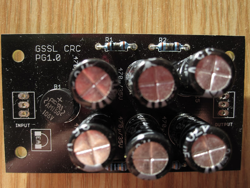
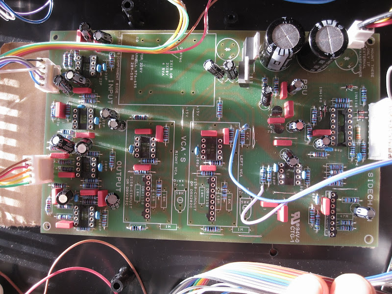
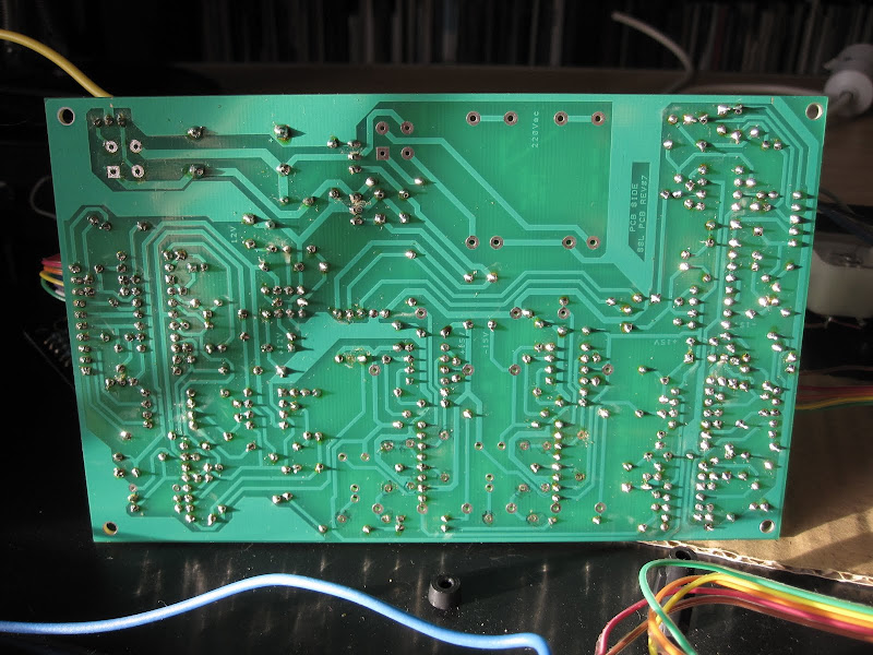
Well, tonight was "The Big Switch On" - needless to say it didn't quite go according to plan... It took only a few seconds to start smoking  so we killed the power. On inspection, 2 of the 10r resistors on the Expat CRC board have burnt out. Anybody know what might be the problem? I presume the wiring from the transformer to the CRC board is the same as going straight to the GSSL motherboard, ie. centre tap (orange & red) to centre hole, black and yellow to the adjacent holes (with the polarity being unimportant due to AC)?
My first instinct was to suspect the rectifier on the CRC board.. if it was faulty would it take out these resistors?
thanks in advance for your help!
PS. I remember once seeing a post in this thread with a diagram showing the Voltage test points - I've been searching for it all day but can't find it can anyone point me in it's direction?
cheers.
so we killed the power. On inspection, 2 of the 10r resistors on the Expat CRC board have burnt out. Anybody know what might be the problem? I presume the wiring from the transformer to the CRC board is the same as going straight to the GSSL motherboard, ie. centre tap (orange & red) to centre hole, black and yellow to the adjacent holes (with the polarity being unimportant due to AC)?My first instinct was to suspect the rectifier on the CRC board.. if it was faulty would it take out these resistors?
thanks in advance for your help!
PS. I remember once seeing a post in this thread with a diagram showing the Voltage test points - I've been searching for it all day but can't find it
can anyone point me in it's direction?cheers.


![Soldering Iron Kit, 120W LED Digital Advanced Solder Iron Soldering Gun kit, 110V Welding Tools, Smart Temperature Control [356℉-932℉], Extra 5pcs Tips, Auto Sleep, Temp Calibration, Orange](https://m.media-amazon.com/images/I/51sFKu9SdeL._SL500_.jpg)