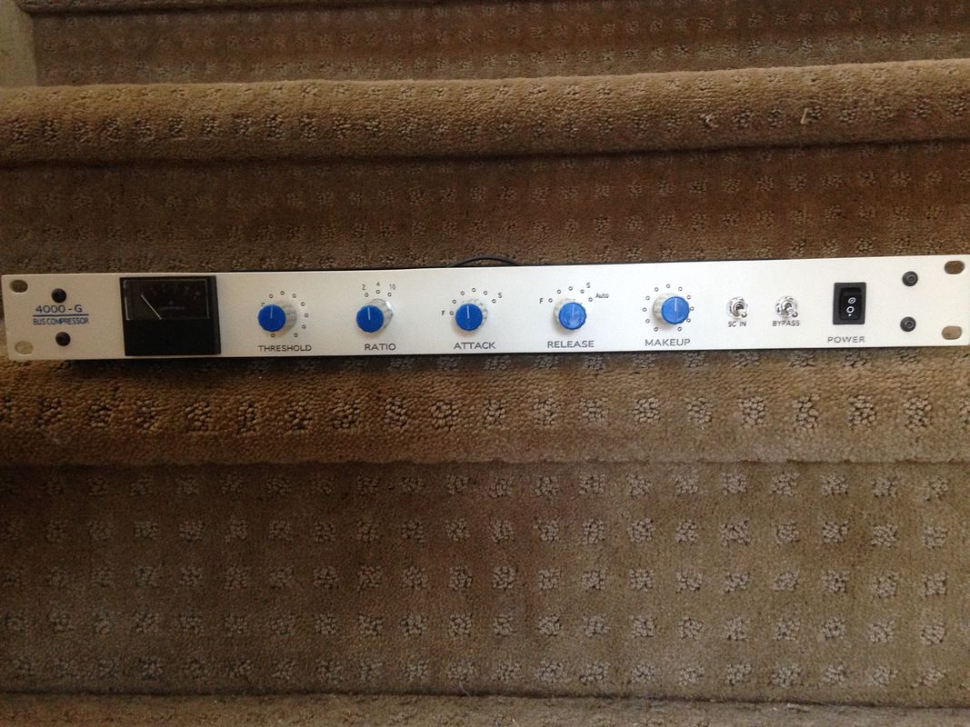
GSSL HELP THREAD!!!

GroupDIY Audio Forum

Help Support GroupDIY Audio Forum:

This site may earn a commission from merchant affiliate links, including eBay, Amazon, and others.
Hey guys, I've been lurking here from time to time and just finished my first DIY project; the GSSL.
Luckily I didn't need much of the advice in this thread, because everything seems to be working very well!
Everything, but one thing; the make-up gain doesn't influence the output signal...
I can't seem to figure it out by the schematics, but I was hoping you guys could point me to where to look for errors.

I've attached a pdf of the pushbutton wiring which I used.
There's two relevant things which may or may not have influenced this problem:

The second pad from top left (which lights the LED) got lifted.
To fix this I soldered it to the pad to its right, because it seems to be on the same trace.
Could someone confirm that this is no problem? Cutting that connection between the two pads didn't solve the problem btw.

There's two unconnected pads in the pdf. In Jakob's guide those were connected to the bypass switch.
Should I leave them like this, put a bridge in there..?

Thanks in advance for the help
 

Attachments

  • SSL_switch_wiring.pdf
    47.2 KB
I finished my GSSL using Gustav's new edition board with the HPF sidechain.
I made the front panel using our laser cutter similar to the method I used for my PMPultec, but I made this one with dual color lettering.  :)

It's all working, and quiet, but I think I want to add the turbo board.
Also, it distorts pretty easily using the "auto" release setting at moderate compression settings. I kind of don't mind this necessarily, but is it normal?

I have a couple questions about adding the turbo board and how it cooperates with the HPF on the sidechain.

I read through Rochey's manual on the expat site, and I'm afraid I still don't really follow how to insert the HPF caps. Would I basically use a DPDT switch instead of the SPST one that's installed now? Add a cap to each leg on the switch then wire the common sides to the respective resistors that correspond before the VCAs as stated in the manual?
I'm not going to use a switch for the turbo, so it will always be in. I don't want to alter the front panel.

thanks for your help!
Eric


Nice build Johnnyscotch, where do the meter come from, and the knobs?
I am about to get started on a GSSL and I am looking for similar things. Looking for Hairball meter among other things.

Did you actually do the cutting of the front panel? Because it looks just like Gustav's template for Front Panel Designer. Neatly done anyway and nice color scheme.

I can't help you much more, but I have 2 other questions:
Is the distortion in auto release normal or do you think you screwed up some adjustements?
Do you want to turbo mod to be on all the time because you are not satisfied with the sound of the comp at the moment with this very SC?
 
thomasdf said:
Nice build Johnnyscotch, where do the meter come from, and the knobs?

meter: http://micandmod.com/en/vu-meters/115-modern-vu-meter-led-gssl-diy.html
knobs: http://micandmod.com/en/knobs/151-g-ssl-knob-blue.html

thomasdf said:
Did you actually do the cutting of the front panel? Because it looks just like Gustav's template for Front Panel Designer.

Have a look at frank's cnc website: http://www.frontpanels.de/miscellaneous-frontpanels/gyraf-g-ssl/
Many different frontplates are available there..

thomasdf said:
Is the distortion in auto release normal or do you think you screwed up some adjustements?

No, there is actually no distortion in the longer release settings. The signal is more likely to distort if you turn the release down very fast together with the attack time..

thomasdf said:
Do you want to turbo mod to be on all the time because you are not satisfied with the sound of the comp at the moment with this very SC?

you can turn it off manually: http://expataudio.myshopify.com/products/gssl-turbo-pcb
 
I know you can turn off the turbo SC, but my question was : why does he want it to be on all the time? Is it because he doesnt like the "standard" GSSL SC?

Thanks for the link, I know Mic & Mods carries the same VU Meter as Hairball, but much more expensive here in France, even with the shipping from the US.
 
Vincent J. said:
...one thing; the make-up gain doesn't influence the output signal...
I can't seem to figure it out by the schematics, but I was hoping you guys could point me to where to look for errors.

I've attached a pdf of the pushbutton wiring which I used.
There's two relevant things which may or may not have influenced this problem:

The second pad from top left (which lights the LED) got lifted.
To fix this I soldered it to the pad to its right, because it seems to be on the same trace.
Could someone confirm that this is no problem? Cutting that connection between the two pads didn't solve the problem btw.

There's two unconnected pads in the pdf. In Jakob's guide those were connected to the bypass switch.
Should I leave them like this, put a bridge in there..?
...

Just for documentation: The two pads on the SSL wiring scheme from frontpanels.de need to be bridged for the make up gain to work.
Period :)
 
thomasdf said:
I know you can turn off the turbo SC, but my question was : why does he want it to be on all the time? Is it because he doesnt like the "standard" GSSL SC?

Thanks for the link, I know Mic & Mods carries the same VU Meter as Hairball, but much more expensive here in France, even with the shipping from the US.

just search online for the meter 8027B or here: http://elektron-sifam.com/meterDetails.asp?modelNo=AL19B
 
Is this meter 1mA DC? Because it looks like a regular VU meter...?

I wasnt very clear, I plan on buying the 8027B from Hairball because even with the shipping cost it is less expensive than buying from Mic & Mod.

I emailed Mike at Hairball asking him if it was easy to open the 8027B in order to change the LEDs (I think white leds are to bright and "cold" and I want warmer LEDs or even light bulbs of an appropriate size). He told me that is was glued and that it may be hard to open it without breaking it. Anybody tried that?
 
Holy crap this is gorgeous! This is a BBC like Peak Meter... Can it be used in the GSSL in order to show up to 7dB of GR? Because I won't be using much more than that...
It must be crazy expensive tho...
 
Thanks,
Meter was from Hairball, knobs from mic and mod

I used Gustavs panel as a template so I could get the spacing correct. I actually laid out my panel in Illustrator, then drilled and printed using a laser cutter. Basically you paint the panel whatever color(s) you want the lettering, then do a top coat and use the laser to etch through the topcoat.

I would like the compressor to perform like it does in the demo video showing the difference between standard and turbo. It works fine, I just prefer the turbo behavior as I witnessed in the video. That's all.

thomasdf said:
Nice build Johnnyscotch, where do the meter come from, and the knobs?
I am about to get started on a GSSL and I am looking for similar things. Looking for Hairball meter among other things.

Did you actually do the cutting of the front panel? Because it looks just like Gustav's template for Front Panel Designer. Neatly done anyway and nice color scheme.

I can't help you much more, but I have 2 other questions:
Is the distortion in auto release normal or do you think you screwed up some adjustements?
Do you want to turbo mod to be on all the time because you are not satisfied with the sound of the comp at the moment with this very SC?
 
Thanks for that clear answer!
Would you happen to have the complete GSSL Sidechain Ed BOM / Part list? I cannot find it anywhere, and I think the on that is on Gustav's website is the regular GSSL's one? (Plus it main contain mistakes..)

Edit: I am also looking for a working schematics of a relay bypass switching that I could do on veroboard... If someone can point me to the right direction? (I don't want another PCB kit)
 
johnnyscotch said:
It's all working, and quiet,
From your pics mains transformer colour coding this might be an AnTec transformer. If so, secondaries look wired out of phase.

Also, it distorts pretty easily using the "auto" release setting at moderate compression settings.
Lorlin end-stop washer set to position 5 ?

I read through Rochey's manual on the expat site, and I'm afraid I still don't really follow how to insert the HPF caps. Would I basically use a DPDT switch instead of the SPST one that's installed now?
The Expat manual relates to different internal or external HPF insertion points (in front of the sidechain VCAs). The internal only HPF on the latest GSSL on board implementation is after current_to_voltage converter before rectification, requiring different cap values for same cutoff frequency because of different resistor values.
For same HPF behaviour as already hooked up, lift one leg of the 22uF cap on turbo board and attach two wires to the lifted caps leg and the freed up hole on pcb. Wires other side go to switch pole and switch throw position of a now DPST switch (a DPDT might be easier to source) with same value cap as fitted for the GSSL HPF connecting to same spots, so the cap is either in series to the signal or shorted out by the switch.
 
Harpo said:
From your pics mains transformer colour coding this might be an AnTec transformer. If so, secondaries look wired out of phase.
Yes, it's an antec trafo. It's not out of phase though. Can you elaborate?


Lorlin end-stop washer set to position 5 ?
again, can you elaborate? I followed the build guide instructions pretty faithfully, maybe I missed something?

The Expat manual relates to different internal or external HPF insertion points (in front of the sidechain VCAs). The internal only HPF on the latest GSSL on board implementation is after current_to_voltage converter before rectification, requiring different cap values for same cutoff frequency because of different resistor values.
For same HPF behaviour as already hooked up, lift one leg of the 22uF cap on turbo board and attach two wires to the lifted caps leg and the freed up hole on pcb. Wires other side go to switch pole and switch throw position of a now DPST switch (a DPDT might be easier to source) with same value cap as fitted for the GSSL HPF connecting to same spots, so the cap is either in series to the signal or shorted out by the switch.
Ok, Thanks, I'll try that when I get the boards
 
thomasdf said:
Would you happen to have the complete GSSL Sidechain Ed BOM / Part list? I cannot find it anywhere, and I think the on that is on Gustav's website is the regular GSSL's one? (Plus it main contain mistakes..

Any help welcome on that matter.

As far as the bypass relays are concerned, I think I have found what I need, I'll keep you guys posted!

Thanks

Thomas
 
Hello my friends,

I gonna build my first DIY project, the GSSL. I´m doing the cart on mouser, I found everything, but I´m in doubt about the ICs sockets and the molex conectors. There are so many opitions and the pictures usually doesn´t correspond to the piece. I don´t want to buy wrong pieces. I hope someone can help me with this.

I need the sockets for those iCs:

NE5532P
NE5534P
TL072IP
TL074CN
THAT2180B

And also the molex conector and cables:

5POLE. PIN connectors, PCB, 1/10" (2.54mm pitch)
10POLE. PIN connectors, PCB, 1/10" (2.54mm pitch)
10POLE connector, Cable, 1/10" (2.54mm pitch)
5POLE connector, Cable, 1/10" (2.54mm pitch)

Last doubt... for what is used those crimp terminals in the gssl project?

16pcs CRIMP TERMINAL for pcb connectors

Thanks,
 
johnnyscotch said:
Harpo said:
From your pics mains transformer colour coding this might be an AnTec transformer. If so, secondaries look wired out of phase.
Yes, it's an antec trafo. It's not out of phase though. Can you elaborate?
from AnTek transformer datasheet (example for a 2x15VAC 50VA) you hook up both secondary windings in series by joining a blue with green secondary wire for the center tap connection.

Lorlin end-stop washer set to position 5 ?
again, can you elaborate? I followed the build guide instructions pretty faithfully, maybe I missed something?
Release switch is designed for 5 step positions. If you don't limit your Lorlin type rotary switch to 5 positions (by removing the fixing bolt, removing the end-stop washer below the fixing bolt, turning the switch full CCW and reseating the end-stop washer to switch pos.5), turning the switch to pos.6 will cause your described artifacts.
 
If you haven't ordered the IC sockets yet, I'd use the rolled pin type. I've always found these more reliable. I have used the alternative type with spring contacts and on one occasion I had a poor contact with one of the IC legs. It took a lot of messing around to find the problem because you just expect these to work first time, all of the time! You can buy a crimping tool for the molex terminals but I have managed to crimp these to the cable using small pliers.
It's a good first build and good luck. You have to be careful because it's habit forming and you'll have racks full of gear before you know it.
Cheers
Steve
 
Thanks for the tips Steve! I´m looking foward to have my racks full of gear! :)

Steve, could you please help me to find the sockets on mouser.com? I´m still doing my chart and there are around a milion sockets with pictures that doesn´t represente the pieces! hehehehe

If you can help me to find a link for the right one would be great! I need all the IC sockets... 8pin 14pin and something to cut for the THAT2180.

Thanks a lot! :)

 
Back
Top