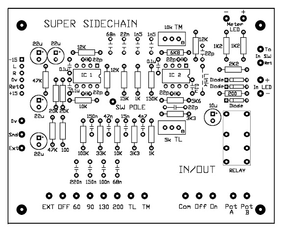
GSSL SuperSC board

GroupDIY Audio Forum

Help Support GroupDIY Audio Forum:

This site may earn a commission from merchant affiliate links, including eBay, Amazon, and others.
audiophreak said:
Hi Stitch-o,

   I got some cloth covered hookup wire from here - http://www.tubesandmore.com/ - he's got a lot of cool stuff, I used the cloth covered wire, tube shields and knobs in my G9.  Its a little bit of a PITA, I had to cut the cotton braid with an exacto knife, then clip the stray threads, but its very heavy duty and I'm glade I used it.

Score!!

Cheers!
 
Little follow up to my install:
It looks like everything is correct in my diagram.
I've been using the comp in sessions this last week: it played like a champ!

One issue has cropped up - the "TM" setting on the SSC does nothing.
I have a new faceplate coming in a couple of weeks so I'll troubleshoot then (and hook up the C'n'B).
But if anyone has any tips in the meantime, I'm always very appreciative.

Cheers!
 
sonicwarrior said:
Ok, the layout has been tested.

If you are interested have a look at the following thread:
http://www.groupdiy.com/index.php?topic=23113

I've set up a page at sdiy.de which is currently only available in german:
http://www.sdiy.de/de/projects/superSC.html

If you have further ideas for improvements: They are always welcome.

Hello SONICWARRIOR

I PM'd you but your box was full, and I dizzily scoured 190 pages of GSSL help thread.

I have just purchased a 06.07.2007 J.Baukhaus GSSL Super Sidechain Filter Rev. A from another member.

Regarding this long ago post, the internal prodigy link is dead. I have been able to see the BOM in the german link, but I am wondering if you still have a wiring diagram for the pcb and related control switches, and if the BOM is still correct.....or if changes have been made.

Thank You.
 

Attachments

  • DSC00010.jpg
    DSC00010.jpg
    54.1 KB
No changes in the BOM and I never had a wiring diagram.

I can translate the german text for the wiring:

---
Connection to the rotary switch:
The complete lower row from "External-SC" to "Super-Med" is connected to the rotary switch.
"Switch" is connected to the middle pin of the rotary switch.
---

Everything else is just normal sidechain business.
 
Thank You very much, that is precisely the information I was looking for. Your board has a very nice wide open layout, and an excellent ground plane. Great work.

kind regards
 
i just installed my SUPER SC Board from Gustav .......but it aint workin:(!   the relay is workin fine and the gssl is compressing fine when i disconect the sc (and re-conect the gssl sum)......but when sc is conected it passes audio but there is no compression at all and if i switch between the modes nothing happens.  I've checked for shorts and there are definatly none. I double checked the wiring and its all good.   Anyone have any ideas??   cheers gerard

*i should add that i'm using NE5534AP opamps.....that shud be ok right?*

*i've also connected the power from the 15v jumper rails ......(i havent connected from the suggested left vca location because i am adding some DBX202s later).....would this be the cause of the problem maybe?

#update# i changed the power connections to the ones at the left vca....yet still not compressing:(


Hopefully by now you will have realised that you should have been using NE5532 op amps NOT NE5534 !
You've probably damaged something because you used single instead of dual op amps.
 
*****!...thanksmate for pointin out that 1.....i did know that the bom stated ne5532...but i assumed that ne5534 would be ok as i used these in the GSSL..i didnt realize they were single ....wat a rookie ********* mistake to make.....cheers
 
well looks like i have damaged sumthin cus it aint workin after putting in ne5532....im guna start by replacing the 22p caps see if that helps.
 
Ok i been testing and trouble shooting and found that the SC board is working (sory it was all along i just sketched out on my switch wiring and got confused). The 12pole switch, thrust/hi-pass filters,relay section are all working fine............. Only thing is that when its wired in my compression level falls by over 10db. So when the SC board is not wired in, my gssl compresses at say -12 to -14db but when i connect the SC board it compresses at about -2 to -4dB even in the off position.    i was thinking of downsizing the 47k's on the SC board so to get a higher level to the sidechain.....but i assume that this comp level drop is not normal and i shouldnt have to do that?  i seen somone had the same problem in this thread in 2007 but he refers to a VR3 ? output trim? which he replaced to fix the problem.  The recent board i got from Gustav doesnt have a VR3 tho? any other solution to this problem? 

thanks, Gerard.
 
A VR3 can be found on my PCB:

superSC-PCB-pre9-teaser.gif


There it sets the Super-Med volume.

Don't know what layout Gustav uses in his PCB.
 
hmm this is the board i have. there seems to be no schematic for it either.
Board%20Layout.jpg


Upon further thread reading it seems the two 20k resistors near the main input are the summing resistors and  not  two 47k (i think). So i guess i could try halving them. But i would of thought that would of been pointed out in the bom/instructions if it was originaly needed so leads me to think the problem is elsewere.

FYI
#i initally powered up the board with NE5534's (mistake ::)) and it didnt pass audio
#i replaced with NE5532N's, board worked fully, apart from the low compression range

 
Ok sorted!  i pulled the board and looking at the tracks it became obvious the L/R are summed at the 20K's and then fed thru the 47K at the return/output. Downsizing the 47K to 12k gave me pretty much identical results to pure gssl mode. Has anyone else had this issue with these specific SC boards? Maybe its an old design from when before the gssl implemented the 47K sum? .........the the board sounds great btw. the thrust filters are really cool and the filter is guna come in mad handy.
 
The information for building and lining up the SSC board is and always has been here:

http://picasaweb.google.com/barclaycon/GSSLSuperSidechainPCB

There isn't a schematic because parts of the design belong to API and they get upset if they think other people are making money from their work.
You don't need the 2 x 47k resistors on the GSSL PCB at all if you are using the SSC board.
If you look at the diagrams and follow the instructions - all will be well.
 
barclaycon said:
The information for building and lining up the SSC board is and always has been here:

http://picasaweb.google.com/barclaycon/GSSLSuperSidechainPCB

There isn't a schematic because parts of the design belong to API and they get upset if they think other people are making money from their work.
You don't need the 2 x 47k resistors on the GSSL PCB at all if you are using the SSC board.
If you look at the diagrams and follow the instructions - all will be well.

All wiring was followed exactly like specified in the instructions which i had downloaded before building. i removed the 47k's on the gssl board...i was using a switch wired with 47k's so i could switch between the SC and initial gssl sum (thru 47k's on switch) so i could tell the difrence in compression level between the 2...SC came out over 10db lower until i changed the 47k on the SC.  I checked all resistors with a meter before soldering them, all solder pads are spot on, correct parts ...so i dont knw why SC was so low..... its sounding great tho with the 12k in there
 
hey all!

just read through the thread but i still couldn`t figure out how to calibrate the THRUST modes on my barclaycon SSC  boards?
I´ve got no VR1,R19,....
got 6 pcs of them for 3 gssls with turbo  ;D
and should i replace the 20k resistors on both boards with 10k (or jumper L+R input as harpo suggested)?
In my wiring both boards are connected all the time with only one input.
as I´ve read harpos wiring he runs through either one of the sidechain boards....

thank you all!
 
hi guys

i have been struggeling to find out how to wire the super SC up. I got the board from Gustav and it is identical with this guide. http://picasaweb.google.com/barclaycon/GSSLSuperSidechainPCB#5193005367618854546 . 

but - i have not gotten a clear answer.  Do I leave my original Bypass switch and wireing and add the new wire from SSC ?

 
mrcase: I'm not an expert but be this is how I calibrated the thrust filters:

In the attached pic (made by another forum-member) you can see that around 500 Hz the response is about the same for all the filters. So adjust the thrust trim so that when you compress a 500 Hz test tone, the gain reduction should be about the same in all SC-settings

I have 2 SC-boards and used 1 10k resistor per board and used only 1 input per board.
If you link the 2 inputs (left and right) you should use 2 x 20k

asle: yes, only use the bypass wiring of the SC-board.
 
Hank Dussen said:
asle: yes, only use the bypass wiring of the SC-board.

so OFF is bypass link it is on the "regular" layout ?  

what is "regular compression then" - meaning disgarding all Super SC and just link the GSSL normally react ?  is that just not possible now ??  

:)


EDIT - toke a long look at the instructions again - and I get it. just needed to understand what went where - off I go
 
I apologize if I my question may sound stupid, but what is this Super Side Chain board exactly for? What does it bring to the GSSL?
Thanks
 

Latest posts

Back
Top