GSSL SuperSC board

GroupDIY Audio Forum

Help Support GroupDIY Audio Forum:

This site may earn a commission from merchant affiliate links, including eBay, Amazon, and others.
Does anyone have a link to a switch for power and bypass that would fit in the Tat case? Barclaycon how about you? I noticed you had them in the excellent pictures of your build...

Thanks in advance,

D :)

 
Well, I used ordinary toggle switches - together with 5mm LED holders for the indication.
Seemed to fit the Tat case fine.

The toggles I got from Farnell : 9473378
The LED bezels were from a local shop but I'm sure they are widely available.
 
Hey guys,

Quick question for anyone who may have tried this.

I am trying to use a separate latching illuminated switch to provide the SSC off, like in the picture.

The Compressor "in" will be driven off the relay and illuminated from the SSC board as usual.

But for the "side-chain" "in" illuminated switch I am planning a second relay to control the "off" position on the rotary.

If I do this however, there is potential for the rotary to be in another position such as 60 or TL when I switch in the "side-chain In" switch. Would this cause a short somewhere on the board. It is hard to see without a schematic.

Mac
 

Attachments

  • comp in ssc in.jpg
    comp in ssc in.jpg
    61.5 KB
mac said:
But for the "side-chain" "in" illuminated switch I am planning a second relay to control the "off" position on the rotary.

If I do this however, there is potential for the rotary to be in another position such as 60 or TL when I switch in the "side-chain In" switch. Would this cause a short somewhere on the board. It is hard to see without a schematic.
The output of the 1st stage summing amp will go to a throw position of your relais for 'filter bypassed', other side throw position of your relais for 'filter engaged' connects to the pole of the rotary switch, relais pole then connects to the 12K resistor instead of the rotary switch pole. For the now useless filter-off position at the rotary you would add a cap for another hpf frequency or fit in other gimmicks.
BTW, you might relabel your switch to "Filter in/out" or "Sidechain Filter in/out" instead of "Side chain in/out".

For the external send/return better use two separate TS or TRS jack sockets instead of a single TRS socket. As long as you only insert another EQ or compressor with a TRS plug, this won't matter, but returning an external source by a TS plug (maybe feed the sidechain with a kick drum signal to key a bass guitar) otherwise would present a heavy load to the 1st summing stage opamp.
 
Hey Harpo, thanks for your help.

Hopefully the attachment will help explain what I am proposing. Did i get your suggested connection point correct?

I dont intend to use the external key connection so I presume I can use this point instead of the output of the NE5532.

I guess the only thing about wiring it this way is that when you have the SSC "In" and you press the Compressor out, the 2nd relay will drop out as well because it gets its 12v feed from the 1st relay.

I dont suppose this is a problem though, because there is no use for a side chain detector when the compressor is in bypass anyway!

Mac
 
Mac,
try it maybe this way* for your EAO-switches.
If you unfortunately have the 6V inscandescent lamp kits (drawing 200mA :eek:), you need to decrease the 2K2 resistors to at least (15V - 6V)/0.2A=45 ohms (probably too bright, I'd try 100R and adjust to taste). These will need a rating of at least (15V - 6V)*0.2A=1.8W to survive, so use a 3W part.
Added a 40Hz hpf position to fill the gap of the previous rotary Off position that now is substituted by your EAO switch.
Good luck

*edit: drawing updated for Multicomp HRS2 relais pinout
 
please is possible to find schematics for the ssc and turbo modes somewhere? or even better, self-etch layouts?
 
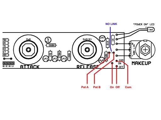
okay guys I'm a little confused about some of the connections...

From the Super SSC board to the Sidechain switch makes sense.  So does the stuff from the main PCB to the sidechain PCB

but:

the 'sleeve' point on the pcb is coming from where?  The 'send' and 'external' I can just leave out if I'm not going to use external sidechaining...is that correct?  And the 'meter backlight' is optional as well, right?

The 'to In SW' or compression switch...that goes to my bypass switch?  And what LED is that right below it, in case I want an LED for bypass? 

'Pot A' looks like the makeup and Pot B is what?  And both the control pcb and the sidechain pcb have 'com' 'off' and 'on' points.  Are these connecting together and then also sending to the bypass switch as pictured in the original gssl pdf?

As you can see...I'm really confused.  I'm staring at the stuff Barclaycon has online but I'm just a little stumped.

Any help?  Anyone have any really clear pictures?  Even the one up on Barclaycon doesn't let me see all that is going on.

Thanks!!

 
Personally, I only use the filter section when I build these.  I leave everything to the right of the "link" jumper unpopulated, because all that stuff is for is a relay-based bypass switching rather than simply a mechanical dpdt bypass switch.  Personally I don't like relays, but that's just my own personal preference.

But, since you asked...
-"Sleeve" refers to "tip, ring, sleeve" as most people use a TRS jack for the send/return similar to a single point console insert.
-"in to sw"...both of those go to your spst bypass switch, as that's all you need for relay based switching.
-pot a and pot b are as below:
Switchboardwiring.jpg
 
regularjohn said:
Personally, I only use the filter section when I build these.  I leave everything to the right of the "link" jumper unpopulated, because all that stuff is for is a relay-based bypass switching rather than simply a mechanical dpdt bypass switch.  Personally I don't like relays, but that's just my own personal preference.

But, since you asked...
-"Sleeve" refers to "tip, ring, sleeve" as most people use a TRS jack for the send/return similar to a single point console insert.
-"in to sw"...both of those go to your spst bypass switch, as that's all you need for relay based switching.
-pot a and pot b are as below:
Switchboardwiring.jpg

Thanks.  I didn't realize the sleeve point was referring to the send/return part though in retrospect I should have.

So pot a and pot b connect to each other? Pot A on control pcb to pot A on super SSC pcb? and same for pot b?  Neither connect to the makeup gain or the filter switch?  Just want to be absolutely clear.  But you helped a lot already! Thanks
 
yes, pot a on gssl to pot a on ssc, and the same with pot b.
they're simply names of convenience for the unnamed solder pads on the gssl.

not to confuse the issue, but if you look at the copper traces they do connect to the wiper of the makeup gain pot, which is why they are referred to as pot a and b.  they just don't connect directly to the pot itself.
 
Thanks a lot.  That makes sense.  This is my first build besides stomp boxes so I'm still trying to get everything straight in my head.  Much appreciated.
 
Hey Harpo,
Got a chance to wire it all up tonight and all went pretty well - relays and switch lights all lit up on cue. I had a minor wiring error which i corrected (dry joint on the +15 rail to the SSC board).

But I cant get the unit to compress. The makeup pot works when comp is switched in just like prior to the addition of the SSC board, but now it doesnt compress anything. The meter twitches slightly when selecting ratios (as it did prior to adding the SSC board), but thats all it does. Passes audio fine, levels are fine, but no compression and no meter. I assumed i must have wired up the on off com a and b points incorrectly but have double checked these and traced them through with a meter from the control board to the relay on the SSC board so they are definitely wired up and making good connections correctly.

Voltages at all the main board IC's etc read normal just like prior to addition of the SSC board, so I am scratching my head a bit.??? Swapped out all three THATs just in case - no change.

Any suggestions where to look next?

Mac
 
Ah Ha!

Dry solder joint on the return from the SSC to the mainboard - and now it compresses with side chain filter engaged. I am using what i thought looked like good quality old stock hook up wire but it is very brittle and you really need to heat it up to get the solder to adhere to it.

But now I cant get the compression to work just with the comp "in" button depressed (in other words just like normal GSSL board without the SSC filter button in)?

Mac


mac said:
But now I cant get the compression to work just with the comp "in" button depressed (in other words just like normal GSSL board without the SSC filter button in)?
Exchange green and yellow wire at the relais.
Sorry for mixing up the pins for this type of relais (they are all different).
 
my pleasure  :)

BTW your mid boost filter question from the other thread.. That's the use of the ssc board external-key position. External-send goes to input of an eq (graphic/parametric, anything in range between rotten stompbox and sontec to shape the response curve of your sidechain signal), eq out goes to external-return/key-in. Now dial in the filter curve to your liking.
 

Latest posts

Back
Top