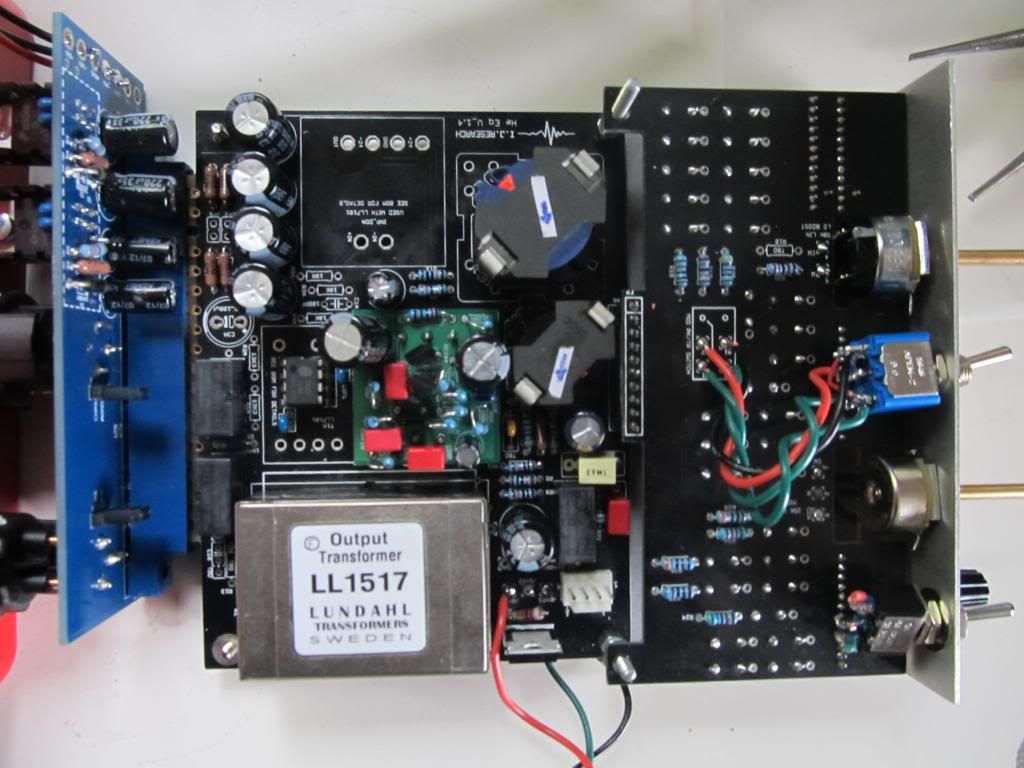
He-69 build/support thread. PCB's/kits-available!

GroupDIY Audio Forum

Help Support GroupDIY Audio Forum:

This site may earn a commission from merchant affiliate links, including eBay, Amazon, and others.
hi igor, just to be sure..i soldered now all the pins on lundahl out tranny, and zobel and load resistor determines if it is 1/1 or 1/2 ?
second..
going to use some 24v doas from pier and he wrote me for best performance of his 2050e on output i should invert C8 and C9.now i wonder if he means swapping the C´s or inverting the polarity on each.. got confused :-\
thanks alot
ax
 
Axelerator said:
hi igor, just to be sure..i soldered now all the pins on lundahl out tranny, and zobel and load resistor determines if it is 1/1 or 1/2 ?
second..
going to use some 24v doas from pier and he wrote me for best performance of his 2050e on output i should invert C8 and C9.now i wonder if he means swapping the C´s or inverting the polarity on each.. got confused :-\
thanks alot
ax

For placing the out trafo, you have pictorial. All pins should be soldered.
If use 1524, load is 1...3k, zobel is 4n7...10n with 200r...1k.

If these opamps have some dc offset and output is about some millivolts...volts to minus, yes reverse polarity of caps.
c9 is 220...1000uf, 16...35v; c8 is 100...200 uf, 16...25v.
Fluke at dc voltmeter range, - to ground, + to opamp's out, and you know exactly what to do with the caps:)
 
anyone finish and try one of these yet? I'm sure they're gonna be great, as Igor is a monster, just curious to hear character and opinions on it.

thanx
T
 
BajenKeno said:
Hey people! I wonder if theres an ~estimated total cost for the kit ($200) and all the parts needed?

Regards /Simon

With pcb's, fronts/lbrackets and inductors from us, you need about $130-240 per one EQ channel.

tonycamp said:
anyone finish and try one of these yet? I'm sure they're gonna be great, as Igor is a monster, just curious to hear character and opinions on it.

thanx
T

Thanx for compliment, I am Addams. Sound talks - "punchy, creamy and crispy". Bah! Hate sound talks.
From my experience. Useful EQ with very different character from most of things I heard. Low boost is the "cool thing" here.
Always works on kick. Can be cool for vocals, too.
 
Igor said:
From my experience. Useful EQ with very different character from most of things I heard. Low boost is the "cool thing" here.
Always works on kick. Can be cool for vocals, too.

Indeed. Finished two (with Igor's help) and the low boost is really something. It does not only boost but add some warm distortion as well. Interesting high end, not the silky EQN, rather adds subtle shine.
 
What did people for knobs? Am looking at available options for those thin shafts.
 
Looking to build this with the THAT chip input option and trafo output.

Anyone done one like this? Any hints/things I should be wary of?

Bit stuck on finding the values for the zobel network - R13, R14, C10 - anyone want to share their values?
LL1517 seems to be most readily available trafo in UK so will use that.

I'm putting together a mouser BOM for this specific option (minus the grayhills, trafo's and a couple of other bits mouser doesn't stock) and would like to get it all in one go (avoid paying lots of p&p!). It currently misses R13, R14, C10. The relays also aren't there as the only suitable ones had a lead time of 23 weeks, so I'll use Farnell for those. Grayhills from Digikey.

http://www.mouser.com/ProjectManager/ProjectDetail.aspx?AccessID=b2048887f3

http://uk.farnell.com/te-connectivity/fx2-d3243/relay-pcb-dpco-5vdc/dp/9913947?Ntt=9913947


For the knobs, Igor wrote this on the 1st page:

"The knobs are ELMA.
In Israel, they are available from local distributor (MOQ = 100+); in small quantities,
these knobs, usually in black, are available from Farnell.
10mm wing knob, 10mm knob, grey, without line, + black skirt with line, + black cap with line; 3.15mm shaft.

The great advantage of these knobs is they are available in sizes 9...45mm for every possible shaft,
can be stacked for concentric pots, can be used with skirt/pointer, etc. Excellent quality BTW.

http://il.farnell.com/jsp/search/browse.jsp?N=2017+202401&Ntk=gensearch&Ntt=elma+knob&Ntx=mode+matchallpartial"
 
This datasheet for the LL1517 seems to suggest that the zobel network isn't necessary:

http://www.canford.co.uk/ProductResources/ig/2735.pdf

(page 2, 'optimum load for best square wave response)

I might see how it goes leaving R13 & c10 out, with 600R for R14.

This would make the mouser BOM above complete, with the following parts sourced elsewhere:

Relays & ELMA knobs (Farnell) , Grayhills (Digikey), Lundahl LL1517 (canford)

Just need to sort out the components for the DOA board that came with it and I\m ready to roll...
 
Almost finished with this build. Just need to wire in the switches, pots and solder the grayhills.

Couple of questions on the grayhills...First, the stop pins. As far as I can work out, just 1 pin is required for each switch, placed in the '6 o'clock' position??

Also, did you have to cut the shafts to fit the elma knobs?
 
Igor,

I'm looking at building these.  Are all of the materials included in your kit? 

Thanks!
David
 
Anyone out there??

Few questions for this build:

Stop pins for the grayhills: As far as I can work out, just 1 pin is required for each switch, placed in the '6 o'clock' position??

Transistors on the HE amp from igor: the BC184 and BC214 are obsolete now...I found this instead of the 184:
http://uk.farnell.com/jsp/search/productdetail.jsp?sku=9556389

But can't find anything for the 214, any suggestions?

hello??
 
HMPS: The kit (if you recieve it) includes the PCB, front panel, inductors, mounting hardware & opamp PCB (if chosen).

You have to source the components yourself. If you look through this thread you might be able to guess that the documentation for it is quite sketchy and support non-existent.

I created a mouser BOM (see this thread) for most of the components. The switches are available from digikey.
My BOM is for the THAT1246 input and I opted for the Lundahl 1517 output.
I had to go to Farnell for the relays - I am still not 100% sure that the ones I got are suitable (from the datasheet they should be...)

Some of the capacitors are unusual values which you might not find in mouser, but I could find all the missing ones (as styroflex caps) on ebay.
 
Ok, I'm going to attempt another couple of questions, although I severely doubt there is any point.

First of all, the obsolete BC184 amd BC214 can still be found on ebay, if anyone is wondering.

My questions:

1. Grayhill switches. On page 2 igor indicated (via the picture I have attached) that the stop pins should go in the 12 and 11 o'clock positions for all switches.
However, this would give 10 positions and both the schematic and front panel seem to indicate that we need 11 positions.
So what is the correct placement for the stop pins?

2. I am unsure of the wiring of the XLR/BYP/INS Switch. Again it is not shown in the 'pictorial'. This should go to BYP1 BYP2 and BYP3 holes on the board, but which order? BYP3 seems to be for the INS, which is the 3rd position on the switch (according to front panel layout), so it should go to the 3rd pin? XLR is the first position, so this should be pin 1? Can you confirm this?
 

Attachments

  • gh_he_stops.JPG
    gh_he_stops.JPG
    76.4 KB
ramshackles said:
.....1. Grayhill switches. On page 2 igor indicated (via the picture I have attached) that the stop pins should go in the 12 and 11 o'clock positions for all switches.
However, this would give 10 positions and both the schematic and front panel seem to indicate that we need 11 positions.
So what is the correct placement for the stop pins?
This makes sense. 1 pin will give you all 12 positions with a stop pin "in between" the first and last positions. 2 stop pins right next to each other will give you 11 positions. Think of the wiper locations as being in between the holes for the stop pins.
 
Hi

I`m about to finish two of these, but I have a hard time sourcing the relays.
Can anybody give me a tips on a relays for this unit?

Also
I`m building these with the HE amp. On the schematic it says to leave out C7 and R11. Is that correct?

Thanks
Mattias
 
Finally finished my unit!

Good news: it passes audio

Bad news: that is all it does :(

It seems like it stuck in permanent 'bypass' mode; audio passes through even when no power is supplied. When I switch the contacts I can hear each relay switching, but nothing changes :(
I measure 16v at the THAT1246, 24V at the DOA and 1.25V at R17 (as it states you should in the docs) when the power is on, which all seems fine.

Any help on where I might be going wrong/other tests I can make?

Pics:


Back
Top