headphone system

GroupDIY Audio Forum

Help Support GroupDIY Audio Forum:

This site may earn a commission from merchant affiliate links, including eBay, Amazon, and others.

bluesbaz

Well-known member
Joined
Jan 9, 2005
Messages
201
Location
San Francisco CA
Headphone mixer.
Ive assembled this thing from data sheet info. I'm sure I've made every mistake in the book but my idea was....
I would like to build a modular headphone system a la Furman hr6, one brain many mixers. I would like to have 10 channels, although the schematic shows only 4.  I have started with the mixer. If I'm way off here I would love some insight on where to look.
Headphone2.jpg
 
A couple of remarks after a quick look, referring to the top channel:

* I'd go with dual opamps. Makes layout easier.
* Why 6 dB gain for the input amp?
* R33 and C7 are not necessary and can be shorted out.
* You want a cap in series with R1 or the pot will become scratchy.
* IC6A and IC6B have positive feedback--outch.
* R4/R6/R7/R8 are unnecessary, short them out.
* IC1B want's a small series resistor (100 Ohm) at the output to isolate cable capacitance.
* With 10 channels you need some sort of make-up gain/summing amplifier.
* Likely you want to arrange the headphone amp with some gain.
* R2/R9 are a bit on the high side for my tast; 33 Ohm should be sufficient.
* Driving low-impedance headphones is asking much from a NE5532.

Samuel
 
There are several subtleties to pick apart but for broad strokes and Sam has already covered these.

a) Your through outputs need a build out resistance (say 100 ohms) to isolate against capacitive loads. While you could in principle eliminate using a separate opamp section to buffer the output, with TL07x opamps you don't have much drive capability margin. They are rated for something like 2k loads, so the parallel impedance of worst case fader and pan settings, and feedback network of input stages means it would only drive relatively high input impedance loads. FWIW, even a dedicated TL07x section is not generally considered robust enough for professional line outputs, while fine for inputs and internal circuitry (IMO).

b) If you have an active input stage you can make it differential, by rearranging your resistors. With a differential network, you can grab your input ground references from the input jack, and forward reference that to a local ground near the fader/pan pots. Adding fixed gain to the input stage could be problematic if driven from a hot source. I'd lean toward using unity gain there.

c) Cap coupling the very input is prudent. DC coupling everything else means DC offsets in the input opamps will show up across the controls. If large enough this can be audible as scratchy sound when pots are turned. C7, etc looks intended to reduce the DC gain of that input opamp but the way the Rs are connected gives a perhaps unexpected result. The BIFET opamps have very little input bias or offset current but will have mV of offset voltage. So the negative feedback connection will drive the negative input pin above or below the positive input pin to this offset voltage for equilibrium. 

For the sake of analysis lets assume a +10 mV offset voltage between +/-. This means at steady state the - pin will be 10mV below the + input.  R 35 has no DC current flowing through it so no voltage drop. This means the full 10mV offset voltage will be developed across R34. Since R32 the feedback resistor must supply this current it will generate a 10 mV drop from - input to output. But since there is no current flowing through R 35, the current in R34 must be supplied by R33. Since these are all the same value this analysis is easy. The end of R33 away from ground will be sitting at -10mV. The + input is also sitting at this -10 mV since there is no current in R35. The - input is sitting 10mV below the + input so -20mV. The feedback resistor drops another 10mV so the output is sitting at -30 mV.  This is actually worse than if C7 and R33 was shorted to ground which would hold the + input at ground, - input at -10mV and output at -20 mV.  For C7 to do any good, you need to connect it only to R34 making the DC current in that leg zero, for a best case of only -10mV output.  Forget my arbitrary 10 mV assumption, the circuit as drawn will deliver 3x the actual offset voltage output across the fader/pan pots. Simple DC coupling is 2x, and proper use of a blocking cap is 1x DC offset.  Note: DC analysis of the 5532 is complicated by bipolar opamp input bias and offset currents. 

d) Without any values shown i can't know how much insertion loss there is in your bus system, but there will be some loss, so you will need make up gain in the final stage . I would also suggest making these output stages differential to reference the local ground at the faders/pan pots, to the output jack.  Note: a common mistake in headphone amp PCB layouts is to not account for the headphone current path. The ground lead for the headphone should have a clean shot to your power supply ground, so it doesn't crosstalk into other circuitry. While not a huge issue in such a simple design, this is a common mistake made by inexperience console designers.

e) I would suggest adding small caps to create a LPF to roll off the input stage at some HF (>>20 kHz). Likewise a small cap to roll off the output 5532 will probably make it more stable, since the 100k feedback R will create a pole with the couple pF input pin capacitance, and socket, and layout capacitance at the node. Another little appreciated benefit of a feedback pole on output stages is improved rejection of RF coming into an output.  The 5532 is adequate for 600 ohm cans or only low level listening using lower Z cans. For serious drive you might want to add some buffer transistors to that output.

Have fun and just do it... while i would dummy up only a few channels before building 10x to see how it acts and learn what needs tweaking...


JR
 
In order to make it able to drive very low impedance like 8 ohms you are going to need something like the TPA6111A2DR from TI.  it's a purpose built headphone driver.  Pretty cheap too.
 
First off thanks so much for any and all suggestions I have tried to integrate as many ideas as possible.
a) Your through outputs need a build out resistance (say 100 ohms) to isolate against capacitive loads. While you could in principle eliminate using a separate opamp section to buffer the output, with TL07x opamps you don't have much drive capability margin. They are rated for something like 2k loads, so the parallel impedance of worst case fader and pan settings, and feedback network of input stages means it would only drive relatively high input impedance loads. FWIW, even a dedicated TL07x section is not generally considered robust enough for professional line outputs, while fine for inputs and internal circuitry (IMO).

This section is only intended to repeat its line input so that I can daisy chain several mixer units together. My idea is to create a "no load" throughput; an opamp split if you will. Is there a more effective solution to consider?

I have left out the headphone amp as I am thoroughly confused. I need a "shitload" of gain here  so the drummer does not complain about not being to hear him self. I generally use MDR7506s in my studio as they seem to be the only phones that can deliver the volume when driven correctly. They are rated for 1wMax@63Ω. Choosing an amp for such an output is the area I could use the most help with. Until I started this thread I thought I could just slap some 5534s together and I would have a headphone amp.
Headphone%20Update1.jpg
 
I don't know if it's a typo or miscalculation, but the o/p stage now has 70dB gain! And the summing amps have too much gain too.
I think you should reconsider the organisation.
I think you should put some gain after the fader to compensate the fader loss (10dB is adequate). This would also provide low impedance source for the pan-pot, which would provide a better law.
As it is the pan-pot has only 1.5dB center attenuation. Although it would not be disastrous because there is no stereo image movement, if you want to conform to the standard -3dB, you need to incease R10 & R11 to 27k. Then you may reduce R8 & R18 to 47k, in order to maintain unity gain (or even lower if you want to improve the summing amp's headroom).
Then, assuming the source level is a normal Odbu-ish line level, you should not need much gain from the output stage. But you need some more drive. The 5532, with a 120R in series with the output, is capable of delivering ca. 75mW to a 32 Ohms load. Reducing the series resistor is no good, because the 5532 would enter earlier into protection.
75mW into a headphone is LOUD, but I've seen some guys crying for MORE. Then the arrangement proposed by gemini86 is capable of significantly more.
You haven't provided a master level control; I think you should, although, from experience, it should have a restricted range, like +/- 6dB. Then, the output stage gain should be a reasonable 20dB.
 
Ok, so I moved things around, reduced the gain in the circuit (forgot to change the values from an earlier project) and integrated the headphone amp section. Do let me know what you all think now. You are all too kind.
mixer4.jpg
 
OK, you got the structure right.
Just a few things need be addressed:
You may need small caps (10-47pF) across the FB resistors on the input and summing stages. make sure you make provision for them on the PCB.
You haven't put a cap between the input amp and the pan pot; I would. When the pots wear out, they might become scratchy.
As I mentioned before, the pan pot law is only -1.1dB at center. Is it really what you want? I would use 22-33k all around.
R22 & R23 wrong value; I suggest 1.5 - 3.3k
You should add a resistor in the output; headphones are designed to take into account a non-zero source impedance (ca. 50 ohms).
I would also add a non-polarised electrolytic 470uF 15V) in the output, just in case one of the output devices goes short-circuit.
C6 & C19 don't need to be so big (47uF would be plenty), don't need such a high voltage rating (16v should be enough).
I see you have gone to pains in putting an additional cap on these electrolytics; why not? There are many discussions on this subject, as many opinions as there are designers, but if you do it on those, you should do it on the others to make sense.
In fact these caps (C6 & C19) are not indispensable. Neither C5 & C14. If I had to chose, I would rather have the output caps and no other electrolytic around this stage. But considering the low cost that makes it a non-issue, I would make provision for them on the board, and experiment later.
On your schematics, I see no provision for decoupling caps. I guess you are aware of the neceesity of those.
 
Abbey Road has good ideas.

If you wanted to keep the 5532 output stage, parallel up the chips.

read this blurb:

http://www.dself.dsl.pipex.com/ampins/webbop/opamp.htm#mult

Personally I would opt for a single headphone driver IC.  they are cheap and you don't need so many external parts like you do in your latest schematic..  Why go through the hassle?
 
IMHO: The "through" jack MUST be a simple wire, NO active parts.

> My idea is to create a "no load" throughput

Sure. But what happens if box B loses power? Boxes C D E... go silent. Much better if only box B goes dead while C D E... keep working.

> My idea is to create a "no load" throughput

What is "NO" load? 10K? 100K? 1Meg? 234Meg? 13 Zillion Gigs? 

The real issue is Level Drop. Does the signal get weaker when more guys plug-in?

Nearly any source you are likely to use will be under 2K output impedance. (If it says it can drive 10K, it is surely <2K out.)

A 1dB change of level is nearly inaudible.

A 20K load on a 2K source causes about 1dB level drop (relative to that fictional "no" load).

You got 10 boxes?

Then make each box input over 200K. Ten of those is 20K total. 20K load on 2K source is 1dB drop, nobody notices.

Can your opamp give 200K input? The TL072 is fine with much-much higher resistors (as long as the stage is not too hot to play on); DC error will be small. The bare chip plus short PCB leads is maybe 10pFd stray capacitance, which is like 1Meg impedance at 17KHz.

BUT: the chip input looks like two diodes to the power rails. When a box loses power, that's like two diodes to ground. If signal levels exceed 0.5V, the source is shorted-out, peaks are clipped.

So use two resistors, say 330K+330K, from input jack to ground, with the chip fed from the junction. Keep the resistors very close to the chip.

When happy, the input is 660K which is over 200K. When un-powered, the input changes from 660K for small input to 330K for large input, but that is still over 200K, and (assuming only one unpowered box) much-much larger than the 20K target for "insignificant loading".

This affair causes 2:1 reduction of level, which you can easily make-up in the same stage.

There is still the real problem that a short at any point is dead all over. When the Marshall Stack falls over and the edge pinches your cable, it will crush and short, and may stay shorted even after the Marshall is lifted.

Your plan does have the advantage that if the B-C wire is crush-shorted, at least A and B can continue working. (You do want some hundreds of ohms on the thru-out, so that box B's buffer does not go crazy driving a dead-short, dirtying-up B's sound.)

From a Systems point of view, daisy-chain is good and bad. If the gang is spread-out along a long line, it minimizes wire. However if the B-C wire is bad, D and E etc go dead. You could alternatively build a main Distribution Box, one in, buffer, ten out. Same number of connectors. Single bad wire means only one box out. Wire length may be 50% higher (for simple cases). At stage-size scale, good connectors cost as much as the raw wire, so daisy chain "savings" is small. And the guy on box J may eventually complain that he is at the mercy of ten cables, and ask why you didn't buy enough wire to reach him directly. Of course ten wires at the Dist-Box can be a mess. My uncle can charge you a lot to optimize such problems, if you can quantify the cost of wire and the cost of failure. My gut feeling, for more than 3 and less than 100 boxes, is that a mix of Daisy and Direct may serve best.

If low-value moderate-Watts pots were readily available, you could avoid all those amplifiers. Run two stereo 100W loudspeaker amps with your four signals. The dist-box is forty 100-ohm resistors. Each user-box is a bunch of 100 ohm pots and 100 ohm mix resistors to the cans. Some estimate and trial-n-smoke labor will be needed to bullet-proof the resistor power ratings. The "pan" network might better be a 5-way switch: you don't need precise stereo placement, and dual-100r 2W pots are rare.
 
Svart said:
Abbey Road has good ideas.

If you wanted to keep the 5532 output stage, parallel up the chips.

read this blurb:

http://www.dself.dsl.pipex.com/ampins/webbop/opamp.htm#mult

Personally I would opt for a single headphone driver IC.  they are cheap and you don't need so many external parts like you do in your latest schematic..  Why go through the hassle?

I agree with you, he could made it simpler.
A few years ago SCA Audio was offering IC replacement for Jensen/Hardy 990 DOA in form of AD797 IC op amp connected to BUF634 current buffer. This combination can drive low ohm loads, i've seen it in several headphone amps, sometimes AD797 was replaced with cheaper op amp.

Miha
 
I used a single chip headphone amp (LM377) in a kit back in the late 70s so this is not new or hard.  That old part is probably long obsolete, but I'm sure there's newer better stuff out there.

JR
 
I've used the one that I mentioned earlier in the thread.  They sound great and are simple/cheap.  No BJT biasing needed or layout of discrete parts, just a simple opamp like part.
 
To be honest it looks a bit like you're sometimes randomly selecting the value of passive components... I recommend printing out schematics and checking all components before posting. Surprising how many bugs you'll catch even when you've become a senior engineer.

A couple of things I spotted on mixer4.jpg:

* R22/R23/R27/R28 are *way* too low. You want about 10k (or as low as 3k) there.
* R12/R32 can be shorted out, they just increase noise and help nothing.
* R26 should have the same value as R20.
* C8/C11 should not need any higher value than 22 pF--more hurts slew-rate and distortion.
* I'd connect C7/C10 to the output of the according opamp instead of the buffer output for better stability. Also I'd reduce their value to 33 pF.
* Even with the buffer I'd recommend small isolation resistors for the headphone amp. 10 Ohm should be enough.
* 60k is not a standard resistor value. 62k is closest.
* I think you've gone too far regarding overall gain; reduce R66/R67 to perhaps 22k.

[Edit: I missed that some of this has been mentioned before, I'm sorry.]

And please use labels for the PSU nets; these long connections are cumbersome to read...

Samuel
 
> single chip headphone amp (LM377) ... That old part is probably long obsolete

It went Lifetime Buy 5 or 10 years back.

My headphone/micromonitor box ate two LM377 in 20 years (I cheated the voltage) so I "sampled" two more to cover me until I retire.

Hah! LM377 was used on Pac Man and other arcade machines.

http://www.arcadechips.com/index.php?cPath=27_22

It may also be available as NTE990.

 
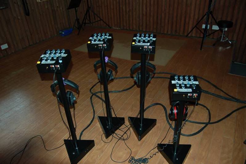
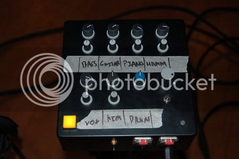
I thought I would share the new Headphone Monitoring System my friend and I have just built.

6 Balanced Mono inputs withe volume and pan
1 Balanced Stereo input with volume
1 mono input fixed at unity (talkback input)
Talkback button with built in microphone
Master volume
Mono switch
L-R Flip switch
1 Watt, Class AB, Class A up to around about 1/4 Watt
Custom stands, 3 for standing musicians and 1 for a seated musician

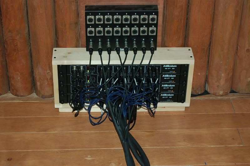
I don't know the details as I am not very good with electronics. I did all of the metal work and stuffed the PCB's. There are 9 small balancing boards for the inputs, the headphone amp and power supply in the mixer, the transformer is in the base. It sounds amazing, I did my first session with the entire system yesterday with a band who had bad experiences at another studio with headphones and were really reluctant but they loved it!

I used 4 off the shelf Millenium 2-8 splitters connected to the 8 buss outs of my mixer. I'm on the look out for some whiteboard style scribble strip if anyone knows where I can get some.

Mixers.jpg


MixerCloseUp.jpg


Splitter.jpg


Latest posts

Back
Top