Joachim Wetzel tube mic

GroupDIY Audio Forum

Help Support GroupDIY Audio Forum:

This site may earn a commission from merchant affiliate links, including eBay, Amazon, and others.
Hi!
Please let us know ... how is succsess on the wetzel. Like to know what it sound like with the capsule back from hospital? A look on one of my wetzels says ... i run into trouble with it ... the capsule is loosing it´s gold - the drill pattern becomes visible. where did you send your capsule for "surgery". How much have you paid for repair? At least one of my Wetzels -the one with the better capsule - sounds great. Compared to a middle-class mic (made in Austria) the wetzel goes to the sun :) and i like to keep them running. The guy i bought the wetzel from said:"It was one of the best for privat recording in area Leipzig/Germany 1968" .....so keep on wetzling.
 
So how did this mic come up in the end?
Did you restore it to original spec, or mod and tweak away at it into something new?
Thanks!
 
It is still not finished, 3 years on.  :-[

I did manage to get the capsule reskinned, but never got round to putting it all back together.

I recall that there were several issues with the power supply - the old diodes were acting very oddly.

Anyway, you have motivated me to dig it out and get it going!

Stewart
 
Hi Stewart,
I'm really happy to have found this thread.

I have one of these microphones and its currently not working, it seems that is something wrong in th PSU.

Where did you sent the capsule to repair?

Is your microphone working at the moment?

THanks, best regards
 
Last edited:
Hi Whoops,

I think it was Dale Ulan who did the repair, but he no longer does capsules. I think one of the board members here took over his business - have a look in the white market.

I am sad to say that I never got round to putting this mic back together. It is still sat in the drawer waiting for the right moment - along with a dozen other projects!

Treat the voltages in my schematic with caution - my mic had a faulty rectifier when I measured them.

Cheers
Stewart
 
Hi Stewart, thanks a lot for your input.

I will try to fix the microphone in the next weeks, I will post here the results.

Thanks
best regards

Tiago
 
Last edited:
zebra50 said:
I am sad to say that I never got round to putting this mic back together. It is still sat in the drawer waiting for the right moment - along with a dozen other projects!

Hello Stewart,
time passes by quickly.

Did you even open that drawer?

I would like to repair my mic,  do you want to finish your repair also and we could help each other in the process?

Thanks
 
Hello,
My Wetzel Mic had a shot power transformer, so I sent it to be rewinded it just came back.
There's no Fuses on the Power supply, so I will install them.

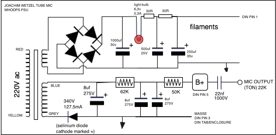
I'm drawing the schematic as my PSU seems to have some differences from Stewart's schematic.

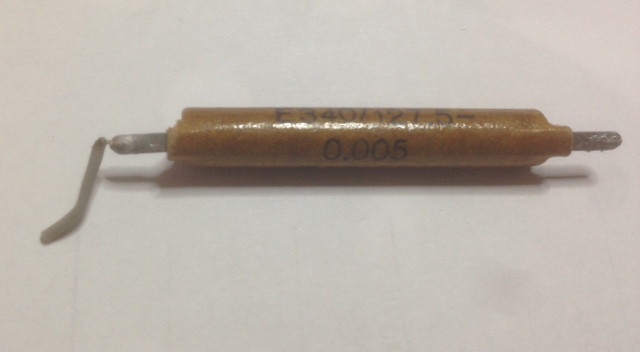
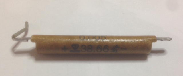
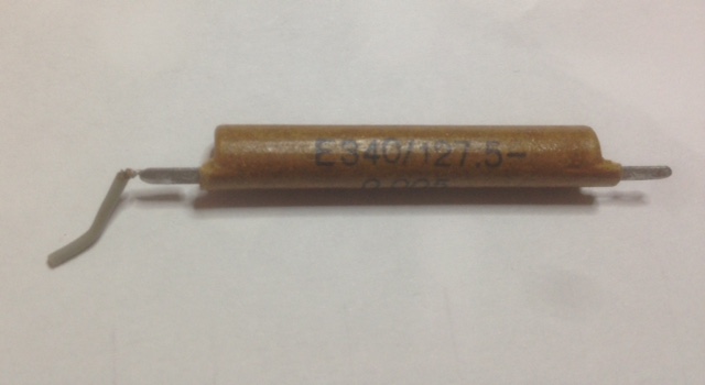
Can anyone please tell me what component is this?

hrtyks1.jpg


luFtKsF.jpg


3WVA715.jpg


My MK-328 says it's a 100pf capacitor
My Peak says it's a Diode
My multimeter doenst measure anything on Diode mode (both ways)

If it's a Diode it seems the Cathote is on it has the + mark, and the anode is on the "-" mark, pretty weird
 
got some info from this website:
https://web.archive.org/web/20131011170727/http://ds-audioservice.de/mikrofone-fotos/mikro2.html

Did a translation from German

"Condenser microphone "System Wetzel 027"
Was built in the 60s by Joachim Wetzel in Leipzig. There were different versions for amateurs and professionals with, or without output transformer. The quality varies greatly due to the production conditions (dust in the capsules!)."


So it seems there were probably versions with an output transformer, for balancing and also lower the output impedance.

I would like to add an output transformer to my microphone,
what transformers would you guys recommend?

thanks
 
here are my voltages of the PSU without the mic connected (unloaded),
my mains power is 230VAC and not the old 220VAC:

Heaters:
after secondary , before Selenium Bridge rectifer: 19.7VAC (zebra50: 20VAC)
Heaters output: 25.6VDC (zebra50: 28VAC)

HT, B+
after secondary: 196VAC
B+ output: 264VDC
 
This is the schematic of my PSU,
looking closelly at the components everything looks original,
I don't see any signs of mods or changes.
I would say it's unthouched although with such an old piece you never know for sure:

Capacitors are Frolyt
Diodes and Rectifiers are Selinium
resistors are pretty old school
everything is point to point (real point to point without any turret or eylet)

FhXRcsE.jpg


Lj9fYxp.png


My PSU circuit has some diferent components and values compared to Stewart's circuit, although both are similar

I had to change the Selinium Diode on the HT rail as it was shot.
The power transformer was shot, it was sent to rewind some years ago, and after the fix it has been sitting on the shelf for some years now, at the moment I don't remember if it was the primary or one of the secondaries that was shorted.

I replaced all the Electrolytic capacitor now, and measured all the remaining  components and connections.

I also installed a Fused IEC plug with Earth connection as the circuit originally had no Fuse protection or mains Earth connection.

 
my microphone came from the previous owner with a TAD ECC83 tube installaed.

There was another ECC83 tube inside the case of the mic that looks it is probably the previous tube installed or the original one.

I tested both tubes in an Hickok and the orange valve tester, and both tubes measure Good.
Maybe the mic stopped working and the previous owner taught replacement the tube would fix it.

I'm tracing the mic circuit now
 
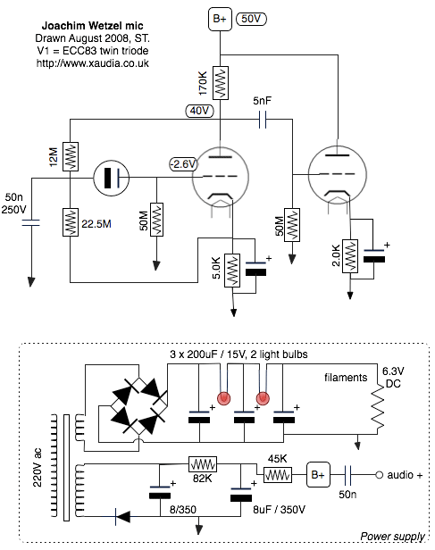
For reference here is the schematic drawn and posted by Stewart in 2008 because the link is gone now:

"Treat the voltages in my schematic with caution - my mic had a faulty rectifier when I measured them.

Cheers
Stewart
"

9pFb0ku.gif

 
I connected the microphone and turned it on.

here are the PSU output voltages with the mic connected, and after the intial volatade ramp up.
Measured after everything became stable:


B+
218V DC

Heater (tube heaters wired for 12V,  6,3V lamp in series with the heater out)
12.8VDC
 
It seems that probably all these Wetzel mic cicuits might differ a litle bit due to revisions/improvments or component availability.

What do you guys think about the circuit schematics?
Do you see things that are worth improving?
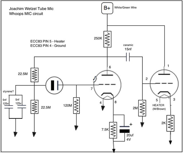
I can see Xaudia schematic has a cap in the Pin3 cathode to ground, also the 22.5M resisitor is connected to Pin8, on my mic is connected to ground.


thanks
 
I don't understand why the audio out is taken from the B+ terminal. This is an attenuated version of the signal at the anode of the first half of the ECC83 and it looks like the second half of the ECC83 is not used at all although it is wired as a cathode follower. Perhaps the output was mean to be taken from the cathode of the second half of the ECC83 via a capacitor and/or transformer?

Cheers

Ian
 
ruffrecords said:
I don't understand why the audio out is taken from the B+ terminal. This is an attenuated version of the signal at the anode of the first half of the ECC83 and it looks like the second half of the ECC83 is not used at all although it is wired as a cathode follower. Perhaps the output was mean to be taken from the cathode of the second half of the ECC83 via a capacitor and/or transformer?

Cheers

Ian

Hello Ian, thank you so much for your help.

I know that these microphones had different versions, and there were Hi-Z unbalanced out, like my mike, and there was also a balanced output versions with a transformer.
Could the second half of the ECC83 be used only for the balanced with transformer versions of the mic?

I can wire it that way, just need to get a proper transformer for it.

In the meanwhile, I discovered that when the transformer was rewinded the primaries and secondaries wire colors were swapped, so I changed the connections accordingly and the voltages are as follows.
The Heater voltage seems to be spot on now.

With mic connected to PSU (230VAC mains power):

B+
Ramps to 338V at power on and then settles at:
218VDC

Heater (tube heaters wired for 12V,  6,3V lamp in series with the heater out)
12.8V
 
Back
Top