LA3A 500 BUILD

GroupDIY Audio Forum

Help Support GroupDIY Audio Forum:

This site may earn a commission from merchant affiliate links, including eBay, Amazon, and others.
kato said:
dmp said:
20 X SOCKETS FOR 1MM PINS        575-029200      0292-0-15-01-06-27-10-0
20 X 1MM PINS      575-311720      3117-2-00-21-00-00-08-0

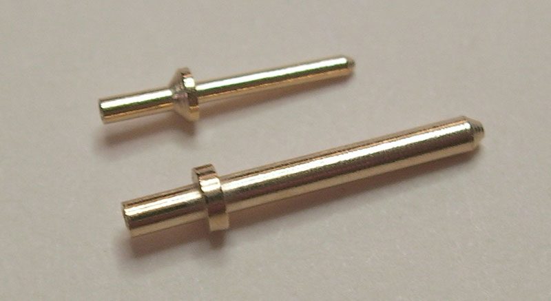
DMP, For what it's worth, the "standard" (?) API style sockets fit the board better and seem a bit heftier. I bought some of each type to compare. Either could work fine but my gut says the 2520 style are worth the extra dinero.  - I'm talking specifically about the mill-max "0334" prefix receptacles - mouser: 575-034420 and pins 575-310320; not the "0322" prefix receptacles Jeff sells at ClassicAPI - which have an 85 mil base and look a hair too big to fit. So I guess it's not really a "standard." (I just don't want to lead anybody to parts that don't fit.) The ones I linked do fit. (As do the ones DMP mentions.)

Here's the difference in size between the two. Either of these will work:

pins.jpg

So I order these is this correct and I will have room for items underneath and for the T4B to sit flush on the LDR's?

https://www.mouser.com/Search/ProductDetail.aspx?qs=2Ods1Gf0wpLvl5YYBpbX8Q%3d%3d

https://www.mouser.com/Search/ProductDetail.aspx?qs=%252b7DTYBcHwZSmZIXkQUOj7Q%3d%3d

What part number can I use for the transistor pads how are people getting them off of the pcb's

Thanks
Scott
 
saxmonster said:
What part number can I use for the transistor pads how are people getting them off of the pcb's

1.9mm thickness
http://www.mouser.com/Search/ProductDetail.aspx?R=501-075virtualkey65330000virtualkey749-501-075

0.5mm thickness
http://www.mouser.com/Search/ProductDetail.aspx?R=511-038virtualkey65330000virtualkey749-511-038

I ordered both to see which is a better fit
 
Did some sorting and building tonight.  Gonna be a fun project.

https://www.dropbox.com/sh/8c85gy1gkw66j5n/8p8Ttx9-98
 

Attachments

  • PCB'S.JPG
    PCB'S.JPG
    671.1 KB · Views: 45
Bornhorst said:
saxmonster said:
What part number can I use for the transistor pads how are people getting them off of the pcb's

1.9mm thickness
http://www.mouser.com/Search/ProductDetail.aspx?R=501-075virtualkey65330000virtualkey749-501-075

0.5mm thickness
http://www.mouser.com/Search/ProductDetail.aspx?R=511-038virtualkey65330000virtualkey749-511-038

I ordered both to see which is a better fit

I just didn't push them flush to the PCBs when i built mine up. you really only need 1mm of space for it to be effective. 
 
Question are D1 and D2 on the output pcb the same as D1 and D2 on the main pcb?  I didn't order two sets crap, or are they different?

 
the baby arrived, so i will start shopping for the other parts.

has anyone tried  the different el panels? do you guys prefer the slow or fast? my understanding is that the slow one is the one closer to the original, right? eventually, how hard would it be to swap them?

thanks
 
Thanks Chuck, I thinking about doing that but had forgot, thanks for the reminder. 

Quick question, can the heat-sinks touch the diodes (CR1 and CR2).  Its so tight in there.  Just wondering if the diodes have juice on the black/grey part or the body of them.  I have all the leads not touching anything but the heatsinks are touching the diode body and maybe the one diode touches one of the cans a bit.


Attachments

  • photo.JPG
    photo.JPG
    360.5 KB · Views: 69
ShandonSound said:
peter purpose said:
Sure, but mine works with it in.

Yea my meter works, the lack of any compression is more of an issue for me!
Could you clarify something else for me please? The solder pads for C14, and one end of R44 and R12 are very close indeed, my solder has bridged these pads, does this matter? Looking at the schematic they appear to be connected, but I'd be glad if you could let me know either way?

Thanks!

Was the issue really with c14 bridging with r44 and r12, cause mine did the same thing and i noticed on the pcb before i soldered that the gold plating had no separation so thats why it bridged and the schematic does show that they are connected.
 
its says 3mm in the beginning of this thread but as I am at the stage now I'm using a 3mm spacer with a 3m nut and lock washer under the pcb.  This allows the front panel trim pot to be in the correct position.  Still working on it I will let you know the exact measurement later tonight hopefully.

 
saxmonster said:
Thanks Chuck, I thinking about doing that but had forgot, thanks for the reminder. 

Quick question, can the heat-sinks touch the diodes (CR1 and CR2).  Its so tight in there.  Just wondering if the diodes have juice on the black/grey part or the body of them.  I have all the leads not touching anything but the heatsinks are touching the diode body and maybe the one diode touches one of the cans a bit.

use your multimeter to test for continuity between the heatsinks and the legs of the diodes.
 
saxmonster said:
its says 3mm in the beginning of this thread but as I am at the stage now I'm using a 3mm spacer with a 3m nut and lock washer under the pcb.  This allows the front panel trim pot to be in the correct position.  Still working on it I will let you know the exact measurement later tonight hopefully.

Turns out to be 6mm spacing for mine. I haven't installed everything but this looks to be right.

 
Ok How do I hook up the meter?  Is the meter the big tabs or the small ones on the back of the meter?  I am thinking that they are the big ones.  Can I attach the capacitor right to the tabs?  I know the meter goes to M+ and M- but what tabs are for the meter.

 
ITS ALIVE, ITS DONE!!!!!!!!!  Need help calibrating though.

http://www.youtube.com/watch?v=7_3znwv5wBQ&feature=youtu.be

Hahaha Great Project.

In Rack

http://youtu.be/TIFziN0hTrk
 
run a -6dbFS sine signal out of your daw (use the daw meters to make sure it's -6) into the module.  crank the squash knob all the way up.  check your results against mine: 

http://groupdiy.com/index.php?topic=42541.msg685261#msg685261

P.S. the results i got with the SA3A were almost identical to the results I got with the LA3A500
 
mulletchuck said:
run a -6dbFS sine signal out of your daw (use the daw meters to make sure it's -6) into the module.  crank the squash knob all the way up.  check your results against mine: 

http://groupdiy.com/index.php?topic=42541.msg685261#msg685261

P.S. the results i got with the SA3A were almost identical to the results I got with the LA3A500

I will do that next Chuck thanks. 

Last night I tried to get R3 to read 1.3kohms.  I had no luck with any combination of the legs. 

So tonight I am still having an issue with R3.  I took the pot/trimmer out.  Dam what a bitch that was. 

Ok so its out and I was able to measure the right two legs and was able to get it to measure 1.3k out of 1976ohms. 

Since the pads are getting rough I install resistor legs into the holes and then soldered the trimmer to the legs. 

When the trimmer is installed I can't get any reading except for 4 or 5 ohms in any leg combination. 

It seems that something is shorting the resistor out.  Could the trimmer be in the wrong way.  it seems that the trace from the middle leg to the right one are connected on the pcb.  The screw on the trimmer is on the bottom edge side of the pcb.

Is this how it should be on should I be able to get a reading with it installed on the pcb.  I can get readings on all the other trimmers that are installed on the pcb.  Just r3 is not reading correctly even though I just adjusted it before I reinstalled it.

What do you think?

 
normally you set that value before you solder it to the PCB, and leave it at that.  there's no real accurate way to measure trimmers while it's connected to other circuitry, i believe.  So when you pulled it out of the board and set it to 1.3k and resoldered it, that should've been all you needed to do, i believe.  You can even see here on ruckus' sa3a schematic that R3 is a plain old 1.3kΩ resistor:  http://dl.dropboxusercontent.com/u/4740474/SA-3A/REV2/SA-3A_REV2_SCHEMATIC.pdf

I believe all that trimmer does is change the level of the signal coming from the input transformer going into the gain knob.  the comp/lim switch just bypasses that resistor or puts it in series.  So, worst case scenario, your unit will permanently be in one more or the other.  I personally can't hear a difference on any of my units (SA3A channels or the LA3A500s) regardless of switch position.
 
Thanks Chuck,
Thats what I did, I just measured it and put it back in.  Don't know why it wasn't giving me a measurement once installed.  Oh well.  I tried your calibration but wasn't sure what I was looking at I am going to have to read up on it more. I don't know what 30 or 50 switch do so I will look that up.  I did turn the squash knob all the way up and sent a -12db signal through it and adjust the boost knob up to where it read -12db on the meters in my daw.  Have to read where to go from there now.  Do I just keep an eye on where the gain knob is?  I did get everything calibrated to what was mention on pg 7 and 21.  Just don't know about the R3 trimmer. 

I am going to need to order thinner bolts to hold the pots to the faceplate.  I will stick the thicker / stock ones on the inside and the new thinner ones on the out side.

 
Back
Top