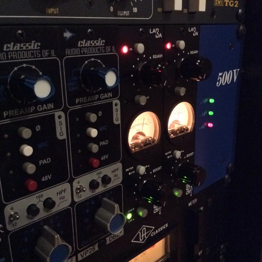
LA3A 500 BUILD

GroupDIY Audio Forum

Help Support GroupDIY Audio Forum:

This site may earn a commission from merchant affiliate links, including eBay, Amazon, and others.
the SA3A's 30/50 switch determines how much gain the Gain knob can provide.  I don't know which format peter's kit is using.  I'm going to guess his is identical to the 30db mode.  Easiest way to find out, run a low signal through it, turn the gain all the way up, see how much you get and subtract it from your original signal level lol

 
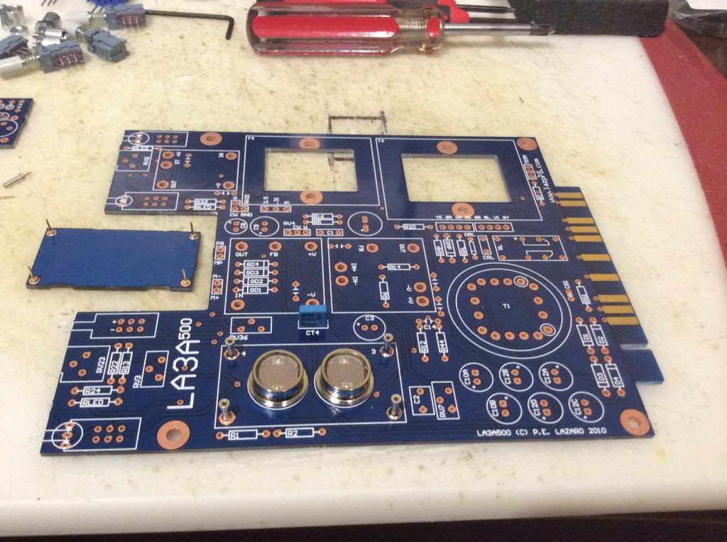
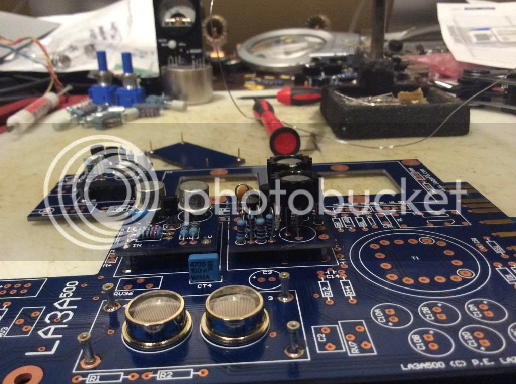
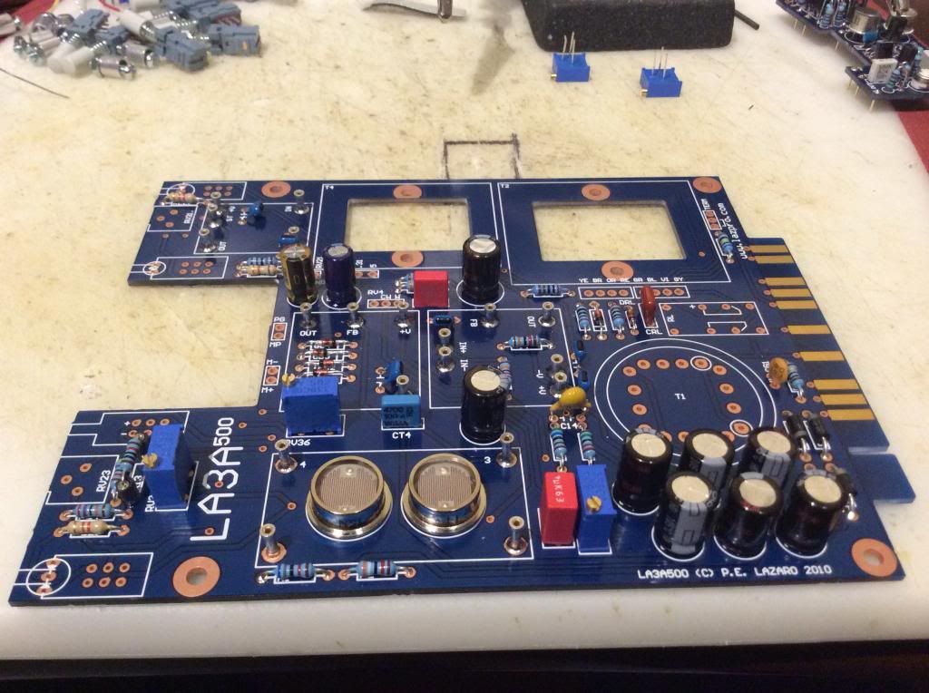
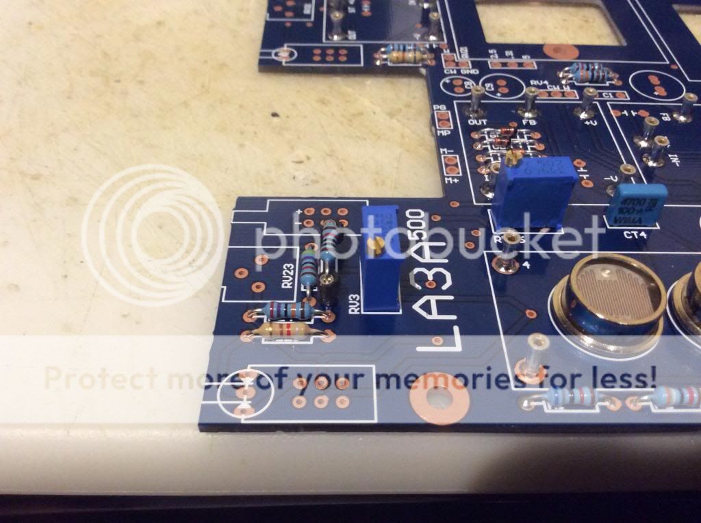
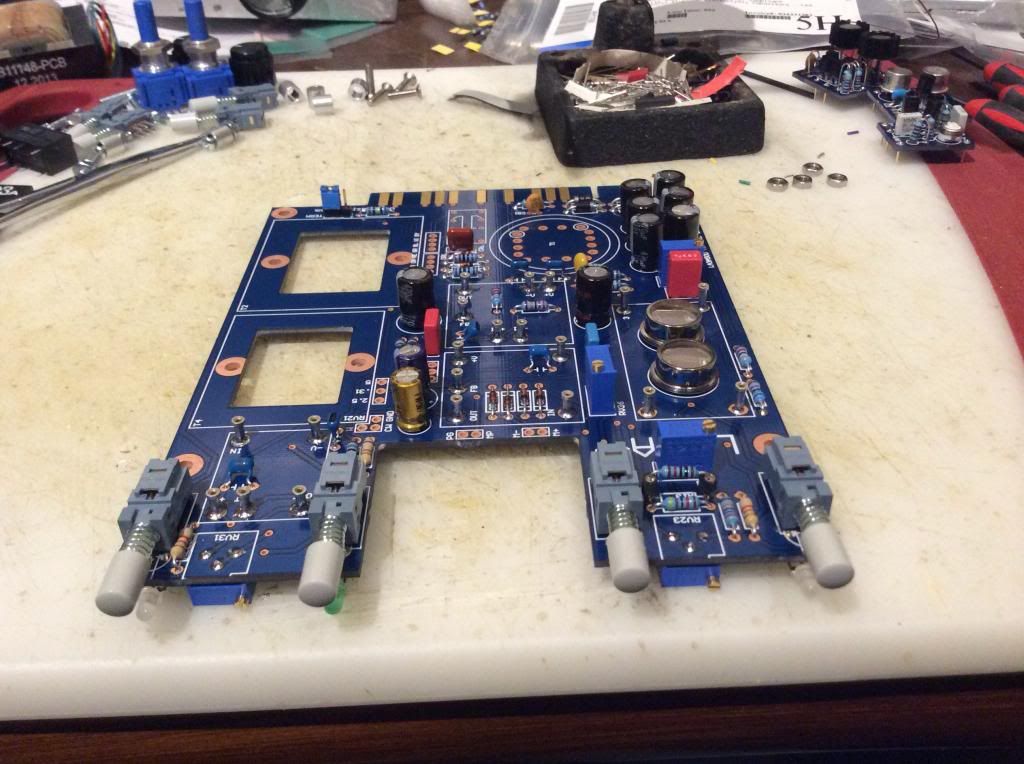
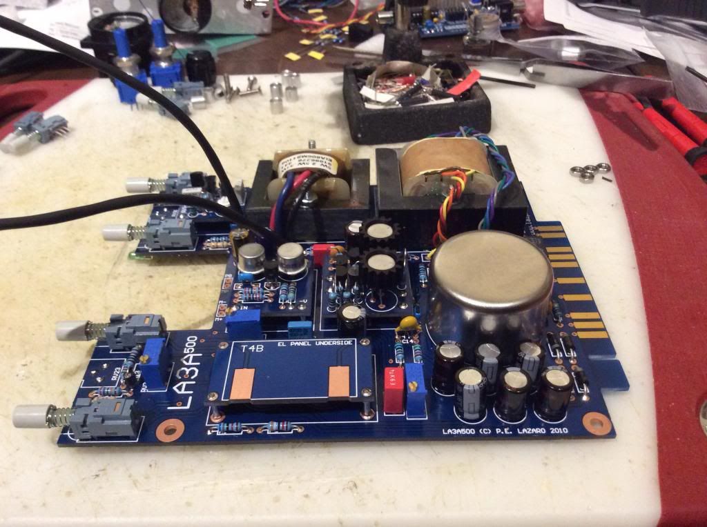
Got all of my parts and started my build last night.  I got the LDRs and the 3 daughter boards finished on each of my 2 units. 

PhotoJan2733317PM_zps6cb3894a.jpg


PhotoJan2791331PM_zps95b352f1.jpg


So I was testing my L3A again this afternoon.

I sent a 1k sine wave out channel 5 of my MOTU 2408MKII and I had to turn the inputs up as they are not the same level at the outputs.  So I had to add about 6db to the inputs so I could get the same reading as the output.  So for my output on channel 5 I had -30db looping back into channel 5 input and After adjusting the input trim to +6db I was able to get -30db with just a standard 1/4 cable, the LA3A was not even in the circuit. 

Here is what it looked liked.

Output channels are on the right, what is my stereo out 1-2 a little lower?


Attachments

  • Screen Shot 2014-01-28 at 4.32.30 PM.png
    Screen Shot 2014-01-28 at 4.32.30 PM.png
    24.4 KB · Views: 8
I then wired up the LA3A into the circuit now that I know the output is equal to the input on the MOTU 240MKII.  So with the LA3A squash turned down I just barley raised the boost knob to get the -30db reading just like the output. 

Here is what that looked like.


Attachments

  • Screen Shot 2014-01-28 at 4.40.17 PM.png
    Screen Shot 2014-01-28 at 4.40.17 PM.png
    22.9 KB · Views: 6
I then turn the boost knob all the way up and got the reading of almost 0db.  I guess the DAW is -1.5 or so and the LA3A meter read 0db.  So I guess this LA3A has about 30db of gain built into it.  Thats pretty cool.

Here is what that looked like.

I now have to get some GR reading so we all can compare.

Have fun.


Attachments

  • Screen Shot 2014-01-28 at 4.42.08 PM.png
    Screen Shot 2014-01-28 at 4.42.08 PM.png
    87.5 KB · Views: 6
So with the squash all the way up here are my readings.

Feeding the LA3A a -30db signal I get 3db of Gain reduction on the LA3A and 2db in the DAW.

Feeding it -24db signal I get 5.5db of gain reduction on the LA3A and 9db in the DAW.

Feeding a -18db signal I get 9db of gain reduction on the LA3A and 14db in the DAW.

Feeding it a -12db signal I get almost 20db of gain reduction on the LA3A and 19db in the DAW.

Do these look ok?

The end points seem equal but the middle is a little weird.  Maybe because the meter is cheaper and not accurate?

What do you guys think?

 
read thru this thread, the meter is not accurate. 

Also, Pan Law will cause signals panned to the center to be (usually) 3db lower than signals panned hard left or hard right.  Plenty of threads about that subject as well  ;)

 
getting close to the end of this - great work peter - thanks so much...

I'm curious - has anyone tried this with an output term resistor?

if so - did you notice a difference?

what value resistor did you use?
 
Some more progress on my build... Ready to install the squash/boost pots and fire it up for smoke test and calibration.

image_zpsec718e84.jpg

Added resistors, caps, diodes to main board. 

image_zps4613e022.jpg

R13 installed in a socket so i can change it out later if needed...

image_zpsaff3b79a.jpg

Installed front switches, LEDs, and trim pots.  Also added output Term header.

image_zpsb37b5d0b.jpg

Transformers, relay, and squash/boost wiring.

image_zps96f4480f.jpg

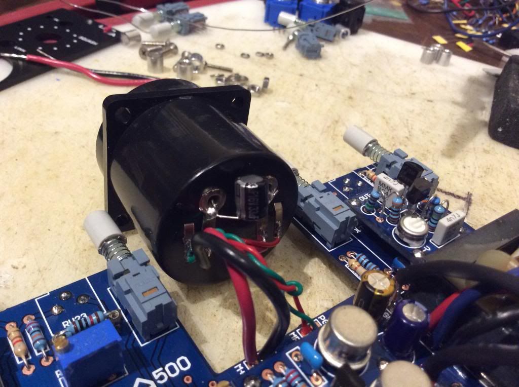
Meter wiring and installed meter capacitor.

image_zps46798018.jpg

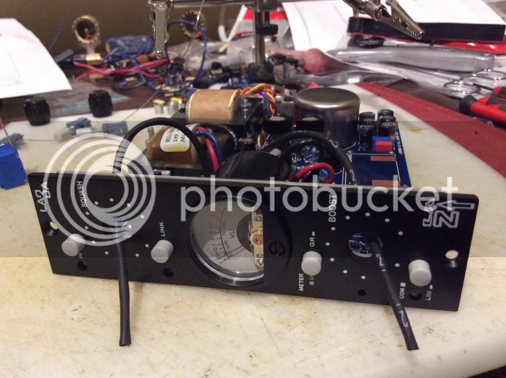
Dry fit test and mounting to sled. 1/4" spacers with 3mm x 12mm flathead screws.

image_zpsb1943a1f.jpg

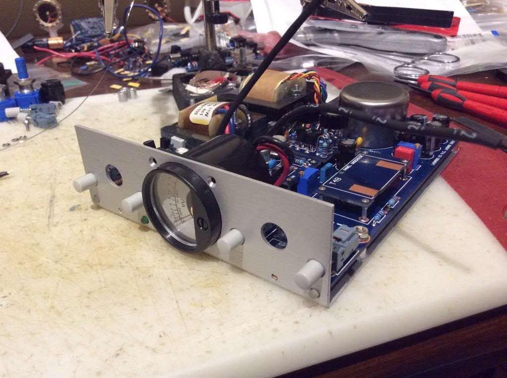
Faceplate installed ready for squash/boost pots!

EL2_zps038e416f.jpg

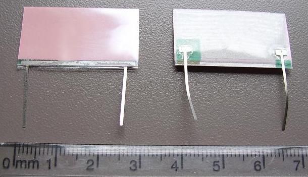
I got these EL panels from Electro Chronic (diypartsstore). Can anyone verify which side is the one that lights up?  Is it the pink side?

 
mutterd said:
getting close to the end of this - great work peter - thanks so much...

I'm curious - has anyone tried this with an output term resistor?

if so - did you notice a difference?

what value resistor did you use?

I will try the output term resistor on my first test. 

I think 604 ohm is listed in the BOM and that is what I used.
 
Pink side is the one that lights up,

Say how did you add multiple pictures to the same post.  Do you have them online somewhere instead of uploading to the groupdiy server?

-Scott

 
saxmonster said:
Pink side is the one that lights up,

Say how did you add multiple pictures to the same post.  Do you have them online somewhere instead of uploading to the groupdiy server?

-Scott

Thanks!

My pictures are hosted in my Photobucket account.  To add more than one I just click on the insert image button and add the link each time... I hope someone along the way will find the pictures helpful during their build  :D
 
Final stretch! Passed smoke test and calibration yesterday.  I spent the rest of the day testing the units out on various tracks.  These are great on vocals and guitars.

I tried mine with the term resistor and without and noticed no real difference.  The only strange thing was while calibrating I used my Minirator MR2 to put a +4dBU (1.228V) signal through them at 1kHZ and the meter does not go to 0VU... It goes to -4VU on both units.

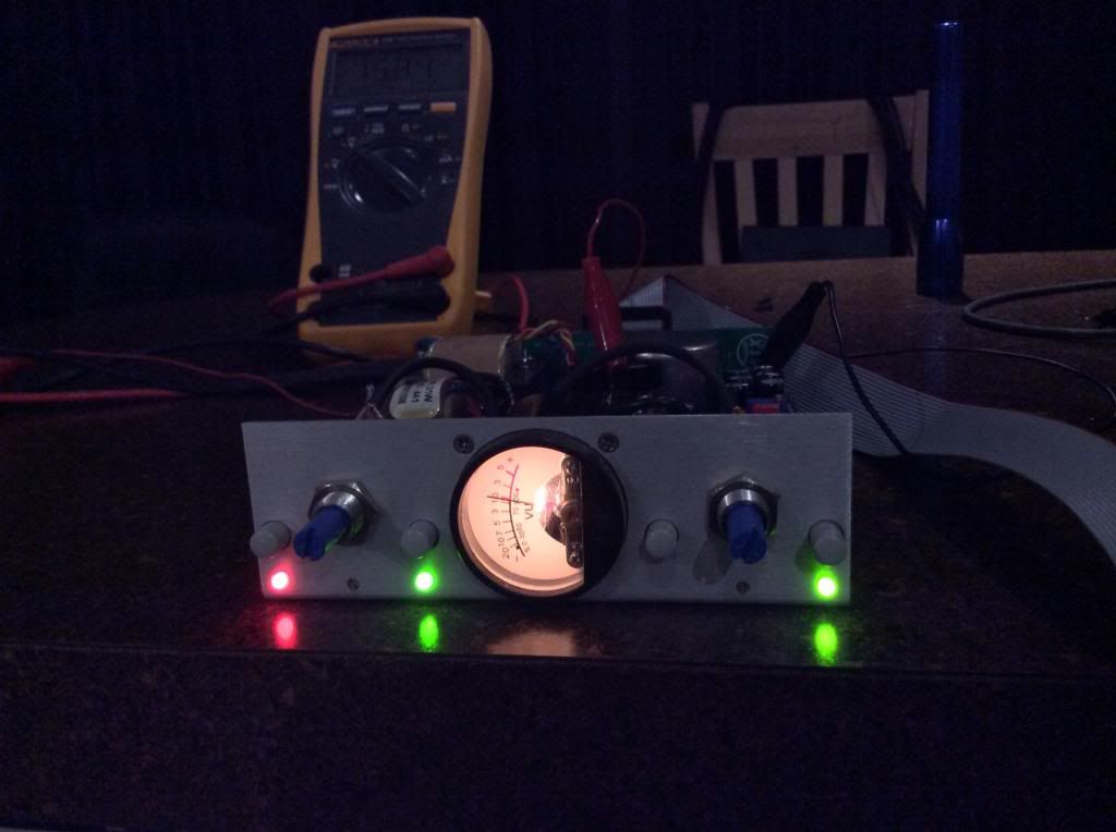
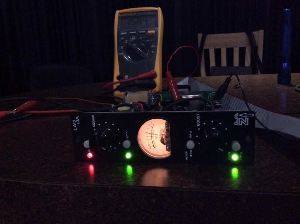
During calibration I tried adjusting RV7 measuring off the top of R18 to ground at D4 and the pot range on both my units is between 14V and 29V... In the pics you can see I settled on 15.84V which sounds great and gives me plenty of good clean boost.

Gain reduction is spot on with my UAD LA3A plugin and the sound is pretty much the same up to about 10dB of gain reduction.  Any more than that and the units start sounding MUCH better than the plugin.

One last thought is that the meter is most accurate between 1dB (-1VU) and 7dB (-7VU) of gain reduction. This makes sense to me because on the meter scale the resolution is only 1dB in between those markings.  Beyond that the resolution between markings is pretty much useless because of the compact size of the meter.  Also factor in that these meters pretty much respond to RMS and not PPM.

image_zps3286d8f8.jpg


image_zpsd3220a8d.jpg


image_zps15da701f.jpg


kdramsey said:
tried mine with the term resistor and without and noticed no real difference.  The only strange thing was while calibrating I used my Minirator MR2 to put a +4dBU (1.228V) signal through them at 1kHZ and the meter does not go to 0VU... It goes to -4VU on both units.

I just did this part this morning and ran a 1khz signal out of my daw an measured the volts to 1.23 and than ran it into the LA3A and the needle stayed at 0db GR.  My squash knob was off and the boost was off too.  Maybe your pots might be bad or don't shut all the way off?  Is this before you zeroed out the meter?  Now when I start to raise the squash knob the meter level starts to show GR based oh how much I turn the squash knob up.  Does yours do that?
 
saxmonster said:
kdramsey said:
tried mine with the term resistor and without and noticed no real difference.  The only strange thing was while calibrating I used my Minirator MR2 to put a +4dBU (1.228V) signal through them at 1kHZ and the meter does not go to 0VU... It goes to -4VU on both units.

I just did this part this morning and ran a 1khz signal out of my daw an measured the volts to 1.23 and than ran it into the LA3A and the needle stayed at 0db GR.  My squash knob was off and the boost was off too.  Maybe your pots might be bad or don't shut all the way off?  Is this before you zeroed out the meter?  Now when I start to raise the squash knob the meter level starts to show GR based oh how much I turn the squash knob up.  Does yours do that?

Try your test with the GR / IO switch in the IO position (not pushed in).  If this switch is pushed in then the meter needle will stay at 0dB unless there is GR occuring.  This is to see the accuracy and calibration of the I/O VU level... +4dBU should equal 0VU on the meter scale when I/O is selected. 

On GR the meter is zeroed and when I raise the squash knob the meter shows spot on gain reduction. And the boost knob gives plenty of clean make up gain so I think all of that is correct.   

 
When I do this the needle stays to the far left, it doesn't move unless I add some boost.  Then I can zero on the meter using the boost knob, then do i take a measurement of what the LA3A is sending out?

 
kdramsey said:
During calibration I tried adjusting RV7 measuring off the top of R18 to ground at D4 and the pot range on both my units is between 14V and 29V... In the pics you can see I settled on 15.84V which sounds great and gives me plenty of good clean boost.

I left mine at 6.5vdc.  That what it said to leave at in the schematic at TP1.  Would leaving it at 15.84vdc hurt it?  Maybe thats why your meter says 0db with the boost knob all the way down?
 
Ok so when I turn up the boost so that I get +4dbu 1.23vdc for the output of the LA3A it does almost read -4db on the meter not quite in the exact middle of -3 and -5 but close enough for me.
 
saxmonster said:
When I do this the needle stays to the far left, it doesn't move unless I add some boost.  Then I can zero on the meter using the boost knob, then do i take a measurement of what the LA3A is sending out?

Let me check what position I have the 'IN' button when I get home later.  The way yours is working might be correct if the 'IN' button is pressed in because that would include the boost and squash circuits in the signal path. 

In the meantime try it with the 'IN' button not pushed in and the GR / IO button also not pushed in. That should bypass the squash and gain circuits via the relay but the meter should still be in the signal path. 

I am not sure I am measuring TP1 in the correct place... Are you measuring 6.5vdc off of the top of R18 on the gain board (the one with the heatsinks)?  Or is TP1 located in another location? 
 

Latest posts

Back
Top